Yaskawa JAPMC-MC2303-E User Manual
Page 91
6.1 Message Send Function
6.1.3 Inputs and Outputs for the Message Send Function
6-6
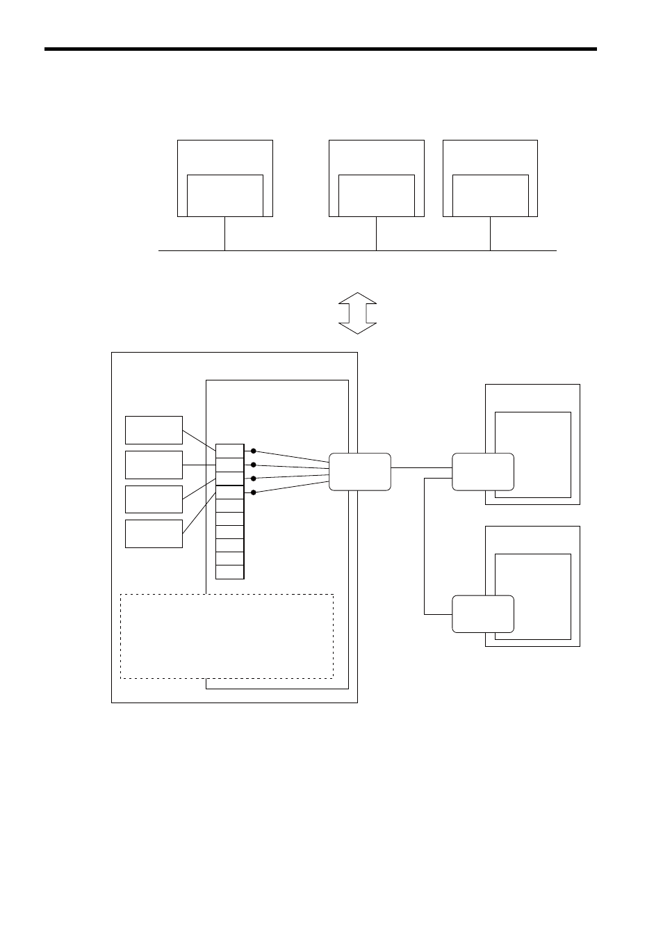
Conceptual Diagram of Transmission Buffer Channels
The following shows a conceptual diagram of the transmission buffer channels.
FL-net node
㩷 㩷
㩷 㩷
㩷 㩷
262IF-01
Node 1
1
2
4
5
6
7
8
9
10
㩷
3
FL-net
㩷
FL-net
FL-net
Node 2
FL-net
port
FL-net
port
FL-net
Node 3
FL-net node
FL-net node
MP2000 Series
Machine Controller
Remote device #1
Remote device #1
Remote device #2
Remote device #2
Network Configuration Diagram
Transmission
buffer channel
MP2000 Series
Machine Controller
MSG-SND
function
MSG-RCV
function
MSG-RCV
function
MSG-SND
function
FL-net
port
The MSG-SND and MSG-RCV functions use the
262IF-01 transmission buffer channels to perform
message communication. There can be no more
MSG-SND/MSG-RCV functions started simultaneously
than the number of transmission buffer channels. In other
words, there can be only one MSG-SND/MSG-RCV
functions started simultaneously for one transmission
buffer channel.