Rose Electronics Orion X-series User Manual
Page 114
106
Orion X Installation and Operations Manual
Connector Pinouts
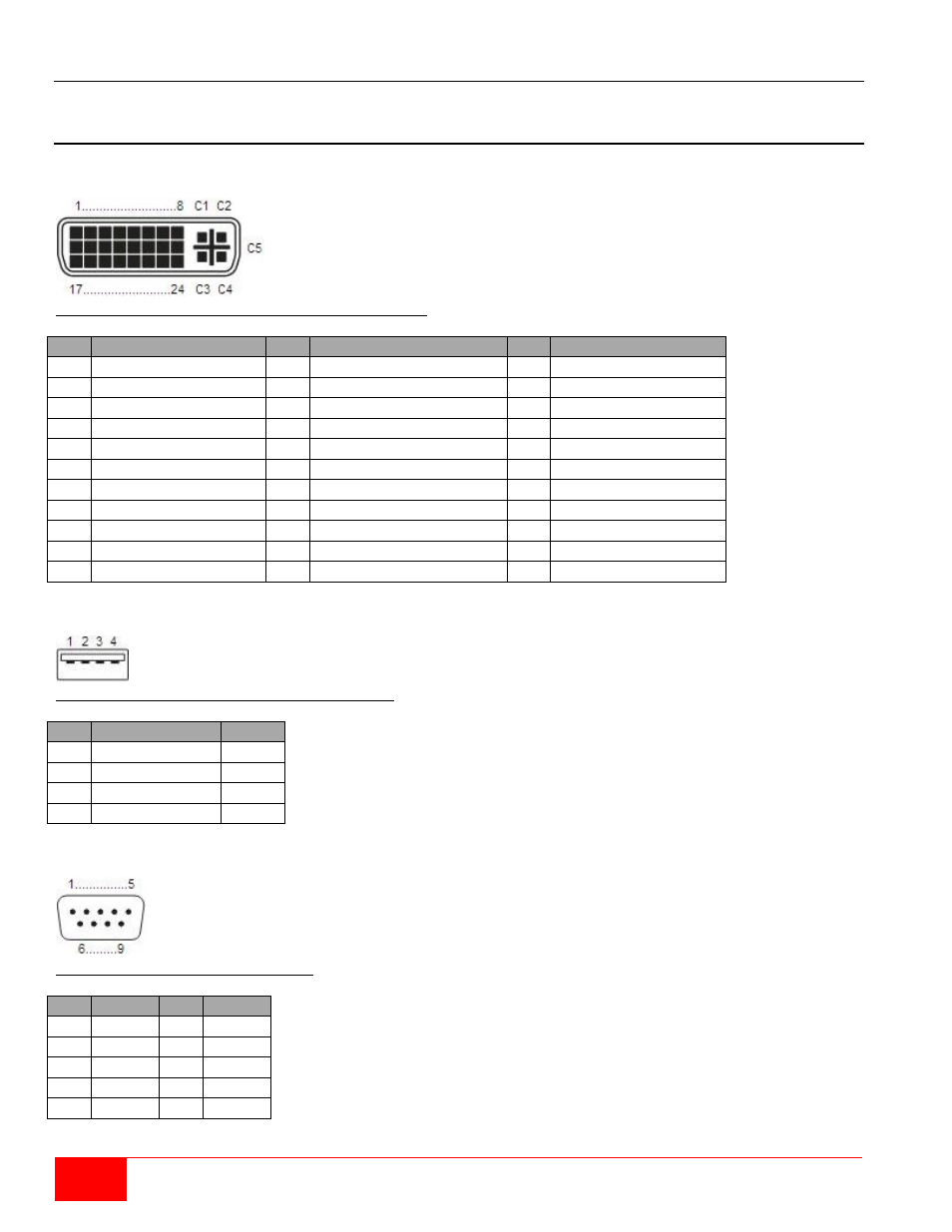
This section shows the pinouts for the connectors on the Orion X.
CPU Board
Connector DVI-D Single-Link
Figure 86. CPU Board DVI-D Single Link Connector Pinouts
Pin Signal
Pin Signal
Pin Signal
1
T.M.D.S data 2-
9
T.M.D.S data 1-
17
T.M.D.S data 0-
2
T.M.D.S data 2+
10
T.M.D.S data 1+
18
T.M.D.S data 0+
3
T.M.D.S data 2 GND 11
T.M.D.S data 1 GND
19
T.M.D.S data 0 GND
4
n.c.
12
n.c.
20
n.c.
5
n.c.
13
n.c.
21
n.c.
6
DDC Input (SCL)
14
+5VDC high impedance 22
T.M.D.S clock GND
7
DDC Output (SDA)
15
GND
23
T.M.D.S clock+
8
Internal use
16
Hot Plug recognition
24
T.M.D.S clock-
C1
Internal use
C3
Internal use
C2
n.c.
C5
GND
C4
Internal use
Connector USB Type A
Figure 87. CPU Board USB Type A Connector Pinouts
Pin Signal
Color
1
VCC (+5V DC) Red
2
Data-
White
3
Data+
Green
4
GND
Black
D-Sub 9 (Serial)
Figure 88. CPU Board Serial Port Pinouts
Pin Signal Pin Signal
1
n.c.
6
DSR
2
RxD
7
RTS
3
TxD
8
CTS
4
DTR
9
n.c.
5
GND