Apple 27" Studio Display (Nano-Texture Glass, Tilt Adjustable Stand) User Manual
Page 53
Studio Display
073-00335-A | 53
© 2022 Apple Inc. All rights reserved.
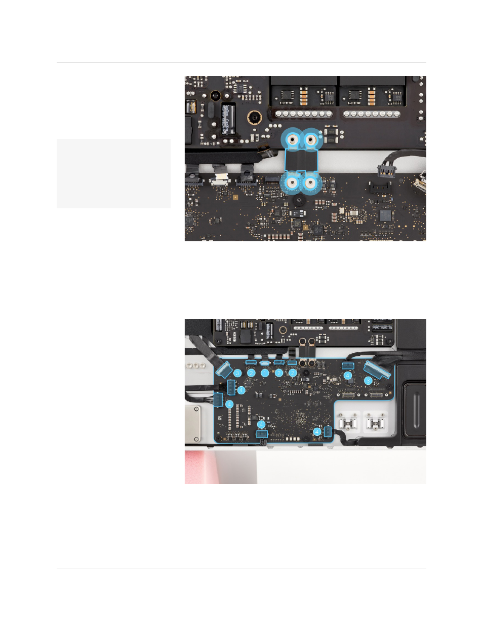
9. Position the logic board bus
bar on the logic board and
the power supply board.
Use the T6 screwdriver to
partially reinstall the four T6
screws (923-07141).
11. Slide the end of the ZIF flex
cable into the connector (1).
Ensure that the cable is fully
inserted.
Logic Board | Reassembly
12. Slide the ends of the three
locking lever flex cables
into the connectors (2).
Then use the black stick to
flip down all three locking
levers. Press the polyester
film tabs to adhere them to
the flex cables.
13. Slide the ends of the two
locking bar flex cables into
the connectors (3). Then
use the black stick to flip
down the locking bars.
14. Slide the ends of the five cables into the connectors (4).
10. Insert the Torx T6 bit into
the 10–34 Ncm torque
driver. Set the torque value
to 20.5 Ncm. Use the
adjustable torque driver and
T6 bit to fully reinstall the
four T6 screws.
Ensure that the hooks
on the bus bar align with
the notches in the logic
board.
Important