Layer 1 clock and reset signals, Layer 1 error signal, Autorate negotiation signals – Altera CPRI IP Core User Manual
Page 111
Chapter 6: Signals
6–13
Physical Layer Signals
December 2013
Altera Corporation
CPRI MegaCore Function
User Guide
Layer 1 Clock and Reset Signals
Table 6–10
lists the layer 1 clock and reset signals.
Layer 1 Error Signal
Table 6–11
lists the layer 1 error signal for the CPRI IP core.
Autorate Negotiation Signals
Table 6–12
lists the autorate negotiation signals for the CPRI IP core. These output
signals enable the autorate negotiation hardware and software outside the CPRI IP
core to quickly monitor autorate negotiation status, and are implemented in all device
families.
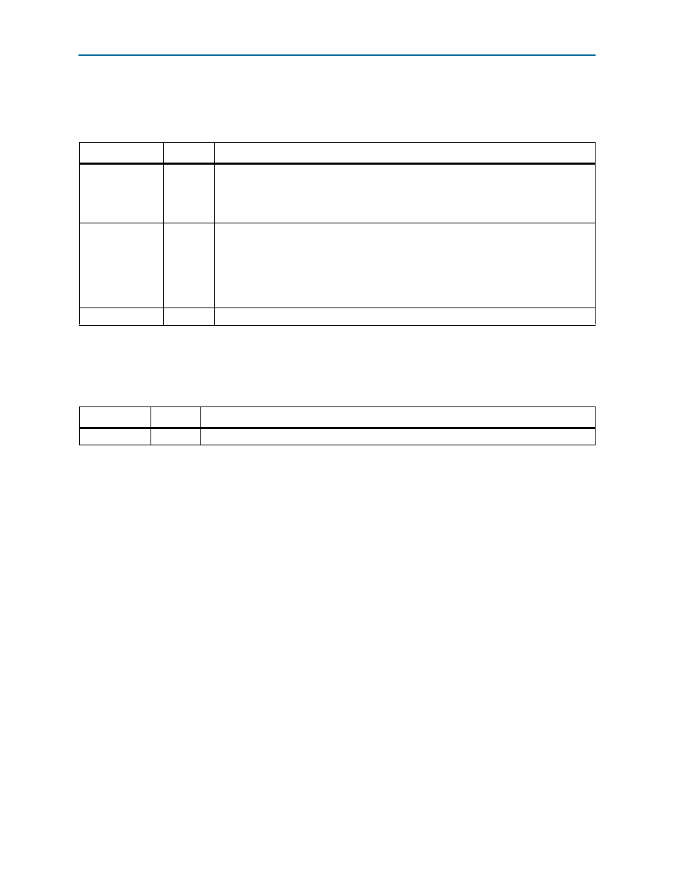
Table 6–10. CPRI Reference Clock and Main Reset Signals
Signal
Direction
Description
gxb_refclk
Input
Transceiver reference clock. In master clocking mode, this clock generates the internal
clock
cpri_clkout
for the CPRI IP core and custom logic.
If the CPRI IP core is configured in master clocking mode, you must drive the
gxb_refclk
and
gxb_pll_inclk
input clocks from a common source.
reset
Input
Transceiver reset. This reset is associated with the
reconfig_clk
clock. A reset controller
module propagates this reset to the CPRI IP core
cpri_clkout
clock domain as well.
reset
can be asserted asynchronously, but must stay asserted at least one clock cycle and
must be de-asserted synchronously with the clock with which it is associated. Refer to
for a circuit that shows how to enforce synchronous deassertion
of
reset
.
reset_done
Output
Indicates that the reset controller has completed the transceiver reset sequence.
Table 6–11. Layer 1 Error Signal
Signal
Direction
Description
gxb_los
Input
Loss of Signal (LOS) signal from small form-factor pluggable (SFP) module.