Altera CPRI IP Core User Manual
Page 51
Chapter 4: Functional Description
4–19
MAP Interface
December 2013
Altera Corporation
CPRI MegaCore Function
User Guide
The MAP receiver interface presents the IQ data on each antenna-carrier interface
according to one of three different synchronization modes. The synchronization mode
is determined by your selection in the CPRI parameter editor and by the value you
program in the
map_rx_sync_mode
field of the
CPRI_MAP_CONFIG
register (
), as shown in
Table 4–7
.
lists the clocks for the AxC interfaces in the different Rx synchronization
modes.
You determine the AxC interface clocks when you turn the Enable MAP interface
synchronization with core clock parameter
on (SYNC_MAP = 1) or off (SYNC_MAP
= 0) in the CPRI parameter editor before you generate your CPRI IP core.
MAP Receiver Interface Signals in Different Synchronization Modes
The different CPRI IP core MAP synchronization modes use different interface
signals.
lists the MAP receiver interface signals used in each of these modes.
Table notes indicate the correct interpretation of the different symbols.
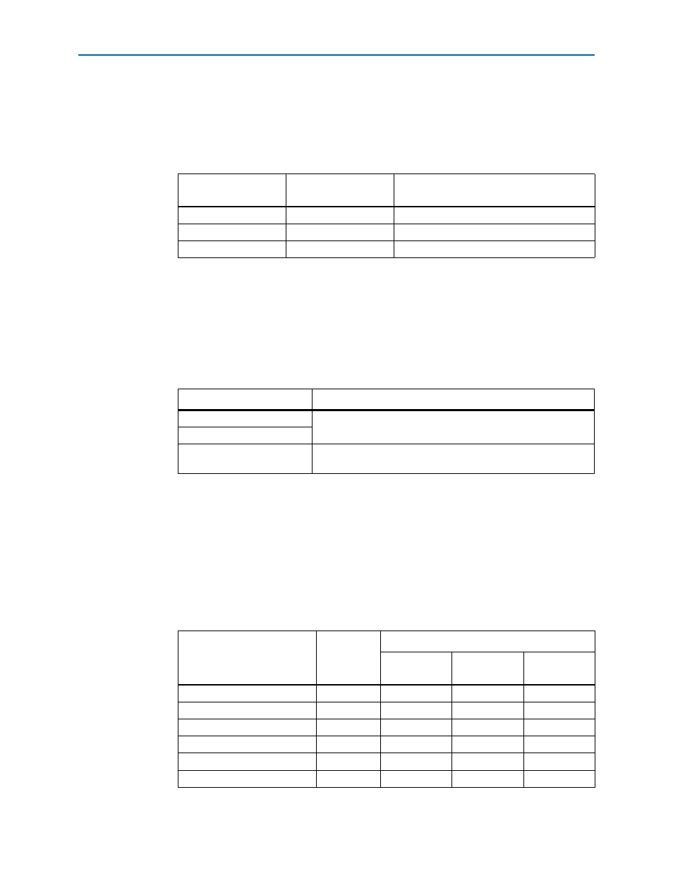
Table 4–7. MAP Rx Synchronization Mode Determined by CPRI_MAP_CONFIG Register Bits
SYNC_MAP
(1)
map_rx_sync_mode
(register bit [2])
Rx Synchronization Mode
0
0
0
1
Synchronous buffer mode (
)
1
—
(2)
Internally-clocked mode (
)
Notes to
Table 4–7
:
(1) You determine the value of SYNC_MAP when you generate your CPRI IP core. Refer to
(2) When SYNC_MAP has the value of 1, the value in the
map_rx_sync_mode
bit of the
CPRI_MAP_CONFIG
register
is ignored.
Table 4–8. MAP Rx Interface Clocks Determined by Rx Synchronization Mode
Rx Synchronization Mode
AxC Channel Clocks
FIFO mode
Each AxC Rx interface is clocked by its own
mapN_rx_clk
clock
driven by the application.
Synchronous buffer mode
Internally-clocked mode
Every AxC interface is clocked by the CPRI IP core clock,
cpri_clkout
.
Table 4–9. MAP Receiver Interface Signals by Synchronization Mode
(Part 1 of 2)
Signal Name
Direction
Available in Synchronization Mode
FIFO
Synchronous
Buffer
Internally
Clocked
map{23…0}_rx_clk
Input
v
v
—
map{23…0}_rx_reset
Input
v
v
—
map{23…0}_rx_ready
Input
v
1
map{23…0}_rx_data[31:0]
Output
v
v
v
map{23…0}_rx_valid
Output
v
v
map{23…0}_rx_resync
Input
—
v
—