Figure d–2 – Altera CPRI IP Core User Manual
Page 177
Appendix D: Advanced AxC Mapping Modes
D–5
Advanced Mapping Mode Similarities and Differences
December 2013
Altera Corporation
CPRI MegaCore Function
User Guide
1
The Altera CPRI IP core does not support the Advanced 3 mapping mode in 16-bit
width mode. Advanced 3 mapping mode does not support spare bytes. Therefore, all
of the data bits in a CPRI frame should theoretically pass through the AxC interface to
or from the CPRI IP core. However, in the 16-bit mode, this requirement would force a
single timeslot to contain information from two CPRI frames, an arrangement the
Altera CPRI IP core does not support.
shows the mapping between CPRI frames and the advanced mapping
tables for a 16-bit mode example. In this example, the CPRI data rate is 1228.8 Gbps
and the value of K is two. For a CPRI IP core running at CPRI data rate 1228.8 Gbps,
the number of data bits in a CPRI basic frame is 240. (Refer to
).
If K (specified in the
K
field of the
CPRI_MAP_TBL_CONFIG
register) has the value of two,
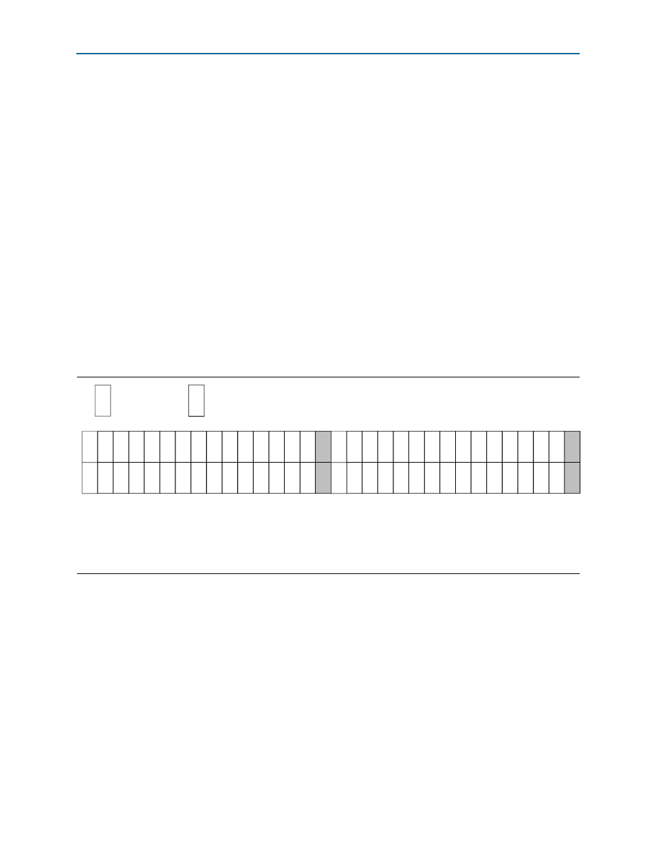
480 bits, or 60 bytes, of data are sent or received on the data channel. The figure shows
how the Advanced 1 and Advanced 2 mapping modes map these 60 bytes in 16-bit
mode.
In the example, the final two bytes of the data from or for each of the first and second
CPRI frames are dropped or assumed reserved. The Rx or Tx mapping table entries 7
and 15 are not valid table entries, as the corresponding IQ data sample is invalid. If
the CPRI IP core has a single active AxC interface, the eighth and sixteenth timeslots
are empty.
Figure D–2. Example of Mapping in 16-Bit Mode
Note to
:
(1) This figure uses the following conventions:
* Each column illustrates two bytes in the CPRI frame.
* The label “c” indicates a control byte.
* A numerical label indicates the index of the corresponding table entry in the Rx or Tx advanced mapping table.
* The label “r” indicates a byte of reserved bits
map mode = 2'b01 and 2’b10 16 -bit samples
c
N
Control Byte
8-bits of timeslot N
c
c
0
0
0
0
1
1
1
1
2
2
2
2
3
3
3
3
4
4
4
4
5
5
5
5
6
6
6
6
r
r
8
8
8
8
9
9
9
9
10
10
10
10
11
11
11
11
12
12
12
12
13
13
13
13
14
14
14
14
r
r
c
c