RLE Falcon EM User Manual
Page 119
User Guide: Falcon FMS
FMS Expansion Cards
www.rletech.com 970
484-6510
105
A-3
CONVERTING CURRENT INPUT CHANNELS TO VOLTAGE INPUT
CHANNELS ON EXPANSION CARD A
When the FMS optional 12 channel analog input card is delivered, its channels are configured for current
inputs (4-20mA). Some sensors, however, may require voltage input channels (0-5V or 0-10V). The
customer may manually reconfigure any or all current input channels as voltage input channels if
necessary.
The headers on the expansion card are labeled P1 through P12. Each number corresponds with a channel
(e.g., P1 corresponds with channel 1, while P10 with channel 10.) Each header has two parallel columns of
five pins. Some pins are connected with jumpers. Changing these header settings converts a current channel
to a voltage channel and vice versa.
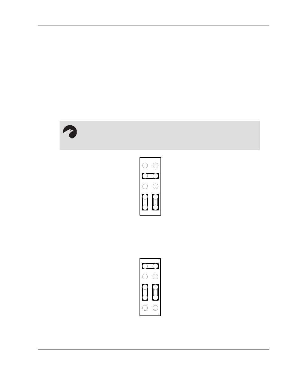
To configure a header as a current channel (4-20mA), connect pins 1 and 3 with one jumper. Connect
pins 2 and 4 with another jumper. Connect pins 7 and 8 with a third jumper.
.
Pin 1
4-20 Ma
Figure A-7: Expansion Card Final Placement in Two Rack Enclosure
To configure a header as a voltage channel (0-5V or 0-10V), connect pins 3 and 5 with one jumper.
Connect pins 4 and 6 with another jumper. Connect pins 9 and 10 with a third jumper.
Pin 1
0-5V or 0-10V
Figure A-8: Expansion Card Final Placement in Two Rack Enclosure
NOTE:
Expansion cards are shipped from the factory with all headers configured as
current channels.