RLE Falcon EM User Manual
Page 38
FMS Configuration
User Guide: Falcon FMS
24 970
484-6510
www.rletech.com
Select Input Type: Select based on the type of device connected to the input channel. Options include:
Not Configured: Select when there is nothing connected to the input.
Analog 4-20mA: Select when the device connected to the input provides a 4-20mA output.
Digital NO: Select when the device connected to the input is a dry contact that is normally open
and closes on an alarm condition.
Digital NC: Select when the device connected to the input is a dry contact that is normally closed
and open on an alarm condition.
Digital Status: Select when the device connected to the input is a dry contact that only needs to
be monitored (status only), without alarms.
Select Input Type:
Physical: This allows users to configure the channel to display a sensor that is wired to a FMS
Input, Channel 1 – 104.
Modbus Import: This allows users to employ a channel to display Modus Register information on
the main page of the FMS. Virtual Slots can be added to the main page of the FMS to display
more Modbus Points; see Chapter 5: Communication, pg. 64.
Gain and Offset: Applies only to Analog 4-20mA input types. Inputs like temperature, humidity,
pressure, etc. connected to the FMS convert information to a 4-20mA signal. The FMS reads this raw 4-
20mA signal and calculates a value based on the input and the predetermined gain and offset settings. The
idea is to determine the correct gain and offset values so that the FMS calculates and displays an accurate
reading. Without setting the correct gain and offset, the FMS will not convert the raw data correctly. As a
result, missed alarms or nuisance alarms could occur.
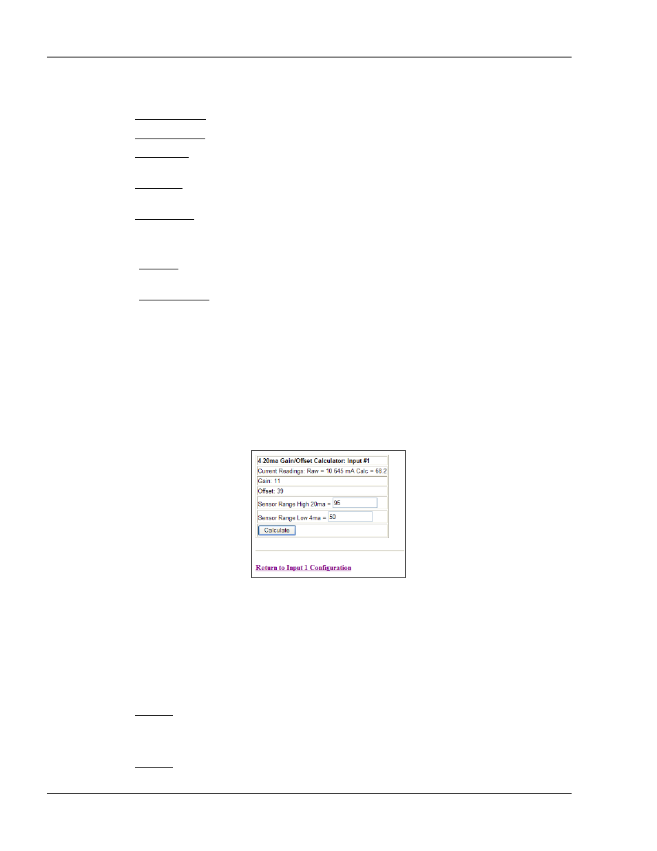
To set gain and offset values, click the Calculator link.
Figure 3-6: Gain and Offset Calculator
Enter the sensor’s range and press the Calculate button. Click the Return to Input 1 Configuration link
so that the gain and offset fields are automatically entered with the correct offset and gain settings. Gain
and offset values can also be determined by using the following formulas:
Gain for 4-20mA Transducer = (Sensor High Range Value– Sensor Low Range Value) / 4
Offset for 4-20mA Transducer = Sensor Low Range Value – Gain
Example: Temperature sensor with a sensing range of 50-95
°
F – displayed in Fahrenheit
Gain = (95-50) / 4 = 11 (round to the nearest integer)
Offset = 50 – 11 = 39
Example: Temperature sensor with a sensing range of 50-95
°
F – displayed in Celsius