RLE Falcon EM User Manual
Page 37
User Guide: Falcon FMS
FMS Configuration
www.rletech.com 970
484-6510
23
3-3.1 Main Board Input Configuration (Channels 1-8)
To configure the FMS main board inputs (channels 1-8), select the appropriate input number. A page
similar to figure 4-3 will appear.
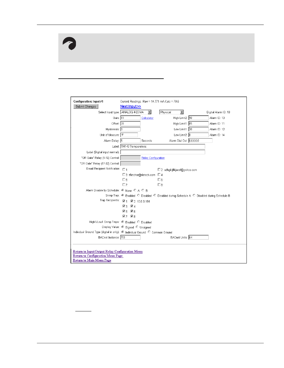
Figure 3-5: Sample FMS Main Board Input Configuration
The number of the input that is being configured will appear in the upper left-hand corner, above the
Submit Changes button. Options on this configuration page are described below.
Current Readings: Displays the input current as sensed by the FMS and the calculated value based on the
offset and gain settings.
Example: The example illustrated above shows a current input of 14.771mA from the temperature
sensor. The FMS converts this value to 79.6°F. When the input Type is Digital NO,
Digital NC or Digital Status, the measured Raw Current Reading will typically be 0mA
or 24mA (depending on input). The Calculated Value will be a 0 or 1, with 1
representing an alarm condition.
NOTE:
Users must push the Submit Changes button after they configure each input. Changes
not submitted before proceeding to the next input will be lost.