Appendix g: relay control logic – RLE Falcon EM User Manual
Page 139
User Guide: Falcon FMS
Relay Control Logic
www.rletech.com 970
484-6510
125
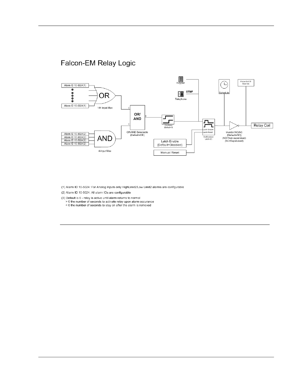
APPENDIX G: RELAY CONTROL LOGIC
Figure G-1: FMS EM Relay Control Logic Diagram
OR Gate 144 Input
The OR Gate can accept any of the High Level 2, Low Level 2 or digital alarms. This option is configured
on each input configuration page.
AND Gate 4 Input
The AND Gate can accept up to 4 alarms. These 4 inputs can be any of the analog level 1 or 2 alarms or
any digital alarm. This option is configured on each relay configuration page.
OR/AND Gate3
This gate uses the OR Gate and the AND Gate as the inputs. This gate may be either an OR or an AND
gate and is configured on each relay configuration page.
On-Delay
This gate will delay the relay operation until the programmed time has expired. The time is configured on
each relay configuration page.
On-Duration/Latch
This gate controls how long the relay will stay activated after a valid alarm combination. A positive number
will allow the relay to stay on for a fixed number of seconds. A negative number will keep the relay
activated for that time after the alarm condition has returned to normal. Zero will force the relay to stay