RLE Falcon EM User Manual
Page 83
User Guide: Falcon FMS
Communication
www.rletech.com 970
484-6510
69
Master Retry Attempts: Determines how many times the FMS will request the same register when there
is no response from the Slave before moving on to read the next register. It is normally left at the default of
one second and is adjustable from 1 to 99 seconds.
Enable Virtual Slot #1-4: Enables additional virtual inputs for use with the FMS main interface. These
virtual points can be used in conjunction with Modbus registers to allow individual alarming, notification
and relay activation per Modbus register.
BCM Zero Amp Level Alarm: Determines if the branch circuit current is zero (CB open or tripped). It is
active when Serial Protocol is set to “Modbus Master BCM – 4 Units” or “Modbus Master BCM – 16
Units”. This applies to all branch circuits in all the BCMs. Each branch circuit has a “Zero Amp” Enable
to enable or disable the zero amp alarm. This setting is adjustable from 0 to 1 Amp.
BCM Status Display: Displays the how the BCM status is displayed (i.e, left/right or vertical).
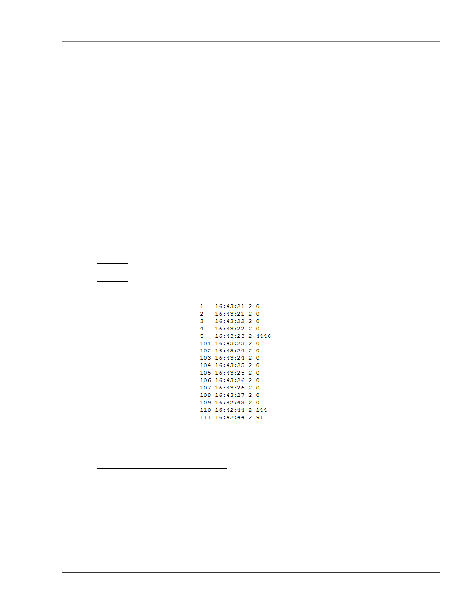
5-3.1 Modbus Master Poll Data Log
This link allows users to view the raw data the FMS receives from the Slave(s). This log is only visible
when the EXP-MBCS option is installed.
Column 1= Falcon Modbus Master Register Number (1-628).
Column 2= Time the Data is received, in HH (hour): MM (minute): SS (second) format where HH is a
number 1-24.
Column 3= Number of Bytes Reserved for Data. This will be 2 unless the Modbus Master register is
configured to read a Long or Float value, in which case it would be 4.
Column 4= Slave Data in decimal form.
Figure 5-7: Modbus Master Poll Data Log
5-3.2 Modbus Slave Register Display Log
This link displays the current contents of the FMS Slave Registers. The rows correspond to the FMS
channel numbers (inputs 1 – 104) with each row containing the Modbus Slave Registers that pertain to that
particular input.