RLE Falcon EM User Manual
Page 16
System Overview
User Guide: Falcon FMS
2 970
484-6510
www.rletech.com
System Status LED
Flashes Red ten times per second during the initial boot up of the FMS, which is approximately
45 seconds. If the initial boot up fails, the LED continues to flash. This indicates a condition that
requires service; users must contact RLE for more information. After the boot up, this LED turns
off if no alarms are present, or turns solid if the unit is in an alarm condition.
Power LED – Green (On) if power is on.
System Power Switch – Used to turn power to the unit on and off.
1-3
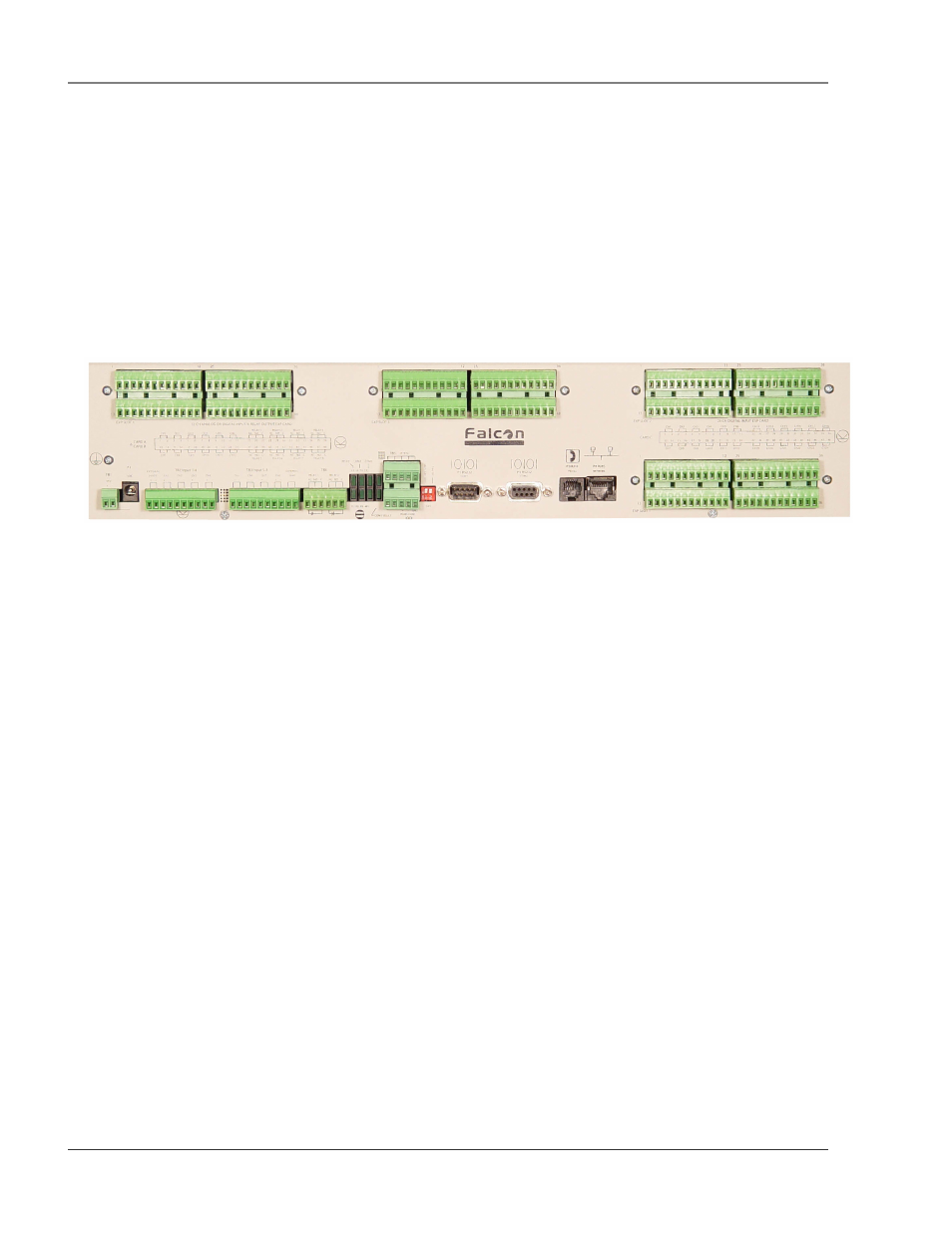
TERMINAL BLOCK DESIGNATIONS
Figure 1-1: Terminal Block Designations
TB1-1 (+) Input for 24 or 48VDC
(optional)
power
TB1-2 (-) Input for 24 or 48VDC
(optional)
power
P1
24VDC wall adapter input (center +)
(not available with 48VDC version)
TB2-1 24VDC positive (+) external output
(power for sensors)
TB2-2 24VDC positive (+) external output
(power for sensors)
TB2-3 Channel 1 positive (+)
TB2-4 Channel 1 negative (-)
TB2-5 Channel 2 positive (+)
TB2-6 Channel 2 negative (-)
TB2-7 Channel 3 positive (+)
TB2-8 Channel 3 negative (-)
TB2-9 Channel 4 positive (+)
TB2-10 Channel 4 negative (-)
TB3-1 Channel 5 positive (+)
TB3-2 Channel 5 negative (-)
TB3-3 Channel 6 positive (+)
TB3-4 Channel 6 negative (-)
TB3-5 Channel 7 positive (+)
TB3-6 Channel 7 negative (-)
TB3-7 Channel 8 positive (+)
TB3-8 Channel 8 negative (-)
TB3-9 24VDC ground external output
(power for sensors)
TB3-10 24VDC ground external output
(power for sensors)
TB4-1 Relay 1 normally closed (NC)
TB4-2 Relay 1 normally open (NO)
TB4-3 Relay 1 common (C)
TB4-4 Relay 2 normally closed (NC)
TB4-5 Relay 2 normally open (NO)
TB4-6 Relay 2 common (C)
TB5-1 Keypad column 1
TB5-2 Keypad column 2
TB5-3 Keypad column 3
TB5-4 Keypad row 1
TB5-5 Keypad row 2
TB5-6 Keypad row 3
TB5-7 Keypad row 4
TB5-8 COM1 EIA485 positive (+)
(configurable)
TB5-9 COM1 EIA485 negative (-)
(configurable)
TB5-10 EIA485 ground
SW1-1 Unit EIA485 termination switch
SW1-2 Reserved for future use.
P2
COM1 EIA232 male DB9 pin
connector
(configurable)
P3
COM2 EIA232 female DB9 pin
connector - craft port
P4
RJ-11 telephone line connector
P5
RJ45 Ethernet 10BaseT connector