Ioioi, 2.4 keypad connection, 2.6 rj11 phone line connection – RLE Falcon EM User Manual
Page 24: Figure 2-6: keypad wiring
Getting Started
User Guide: Falcon FMS
10 970
484-6510
www.rletech.com
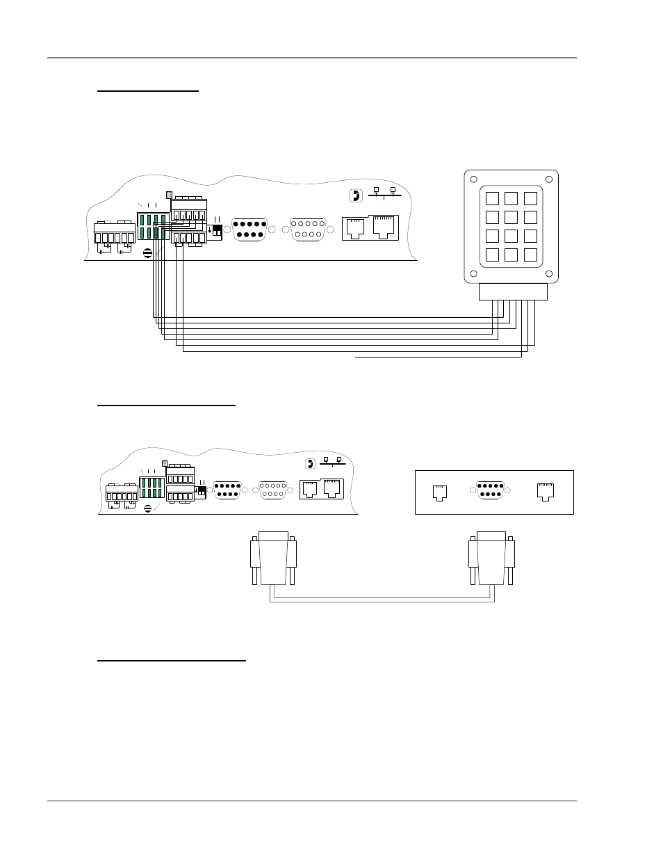
2-2.4 Keypad Connection
The FMS has a 3 x 4 keypad interface. Entering a user code, configured through software, can activate a
relay output which unlatches a door and allows an individual to enter the secure area. Entering the correct
user code can also trigger a relay output to signal an IP camera to snap a picture and email it to a predefined
recipient. Connect the keypad as shown in Figure 2-6. For more information on configuring the keypad
function, see section 3-17 Keypad/DTMF Access Users on page 45.
P4 RJ11
TELCO
P5 RJ45
NETWORK
IOIOI
P3 RS232
COM2
IOIOI
P2 RS232
COM1
SW1
+ - GND
RS485 COM1
IOIOI
COM1 SELECT
K2 RX RX 485
K1 TX TX 232
RELAY COM1 COM2
48
5 T
E
R
M
SE
L M
/S
TB5 KEYPAD
TB4
NC NO C
RELAY 1
NC NO C
RELAY 2
1 2
ON
1
2
3
4
5
6
7
8
9
*
0
#
Pi
n 1
Pi
n 2
Pi
n 3
Pi
n 4
Pi
n 5
Pi
n 6
Pi
n 7
Pi
n 8
RLE - KPO Keypad
Falcon TB5-1
Falcon TB5-2
Falcon TB5-3
Falcon TB5-4
Falcon TB5-5
Falcon TB5-6
Falcon TB5-7
Keypad Pin 3 - Orange
Keypad Pin 4 - Green
Keypad Pin 5 - Grey
Keypad Pin 1 - Red
Keypad Pin 2 - White
Keypad Pin 8 - Yellow
Keypad Pin 7 - Blue
Keypad Pin 6 - Black
No Connection
Column 1
Column 2
Column 3
Row 1
Row 2
Row 3
Row 4
Figure 2-6: Keypad Wiring
2-2.5 EIA232 COM2 Connection
The EIA232 port can be connected to a PC for IP configuration, firmware downloads, and troubleshooting.
It is typically a temporary connection. Connect the straight through, 9-pin, cable as shown in Figure 2-7.
(Male)
Back of PC or Laptop
(Male)
(Female)
RS232 Cable (Straight Thru - Shipped with Falcon)
COM PORT
Modem
LAN 10baseT
P4 RJ11
TELCO
P5 RJ45
NETWORK
IOIOI
P3 RS232
COM2
IOIOI
P2 RS232
COM1
SW1
+ - GND
RS485 COM1
IOIOI
COM1 SELECT
K2 RX RX 485
K1 TX TX 232
RELAY COM1 COM2
48
5 T
E
R
M
SEL M
/S
TB5 KEYPAD
TB4
NC NO C
RELAY 1
NC NO C
RELAY 2
1 2
ON
(Female)
(Male)
Figure 2-7: EIA232 COM2 Connection
2-2.6 RJ11 Phone Line Connection
The FMS contains an internal modem for dial in and dial out capabilities. The modem can be used for:
Email notification through an Internet Service Provider (ISP).
Remote connection to accomplish a variety of tasks, including: viewing alarms, changing IP
configurations, and acknowledging alarms.
Remote alarm acknowledgment and access through DTMF. This allows a user to dial the FMS
from a touch tone telephone—standard phone or cell phone—and enter an acknowledgment code or
access
code.