Appendix h: expansion card b, H-1.1 expansion card b connections, Figure h-1: expansion card b i/o terminals – RLE Falcon EM User Manual
Page 141: Figure h-2: typical wiring for expansion card b
User Guide: Falcon FMS
Expansion Card B
www.rletech.com 970
484-6510
127
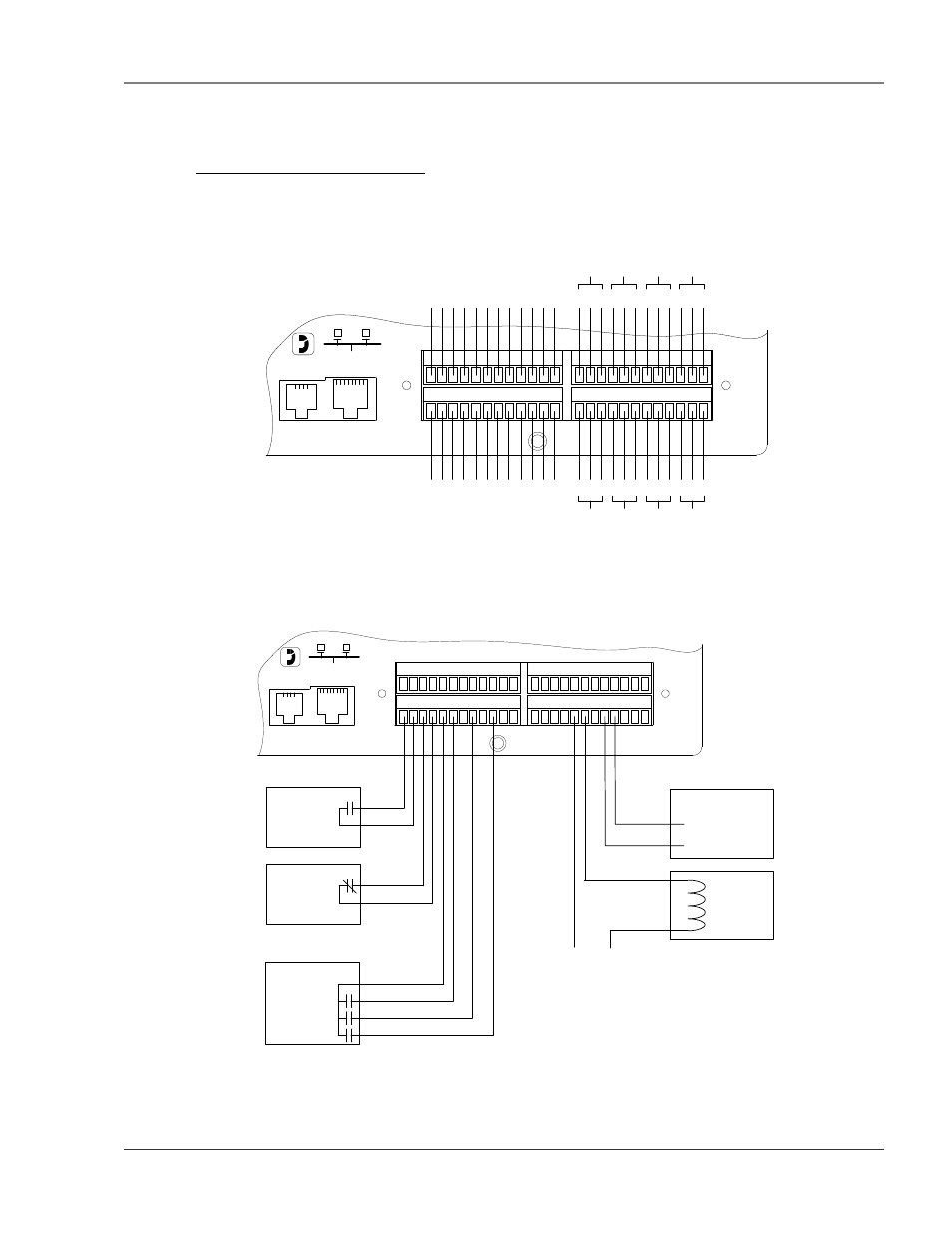
APPENDIX H: EXPANSION CARD B
H-1.1 Expansion Card B Connections
Expansion Card “B” has 12 dry contact input channels and 8 relay output channels.
48
24
37
12
25
36
13
1
EXP SLOT 1
P4 RJ11
TELCO
P5 RJ45
NETWORK
NC
NO
C
+ -
Ch 1
+ -
Ch 2
+ -
Ch 3
+ -
Ch 4
+ -
Ch 5
+ -
Ch 6
Rel
ay
1
NC
NO
C
Rel
ay
2
NC
NO
C
Rel
ay
3
NC
NO
C
Rel
ay
4
NC
NO
C
Rel
ay
5
NC
NO
C
Rel
ay
6
NC
NO
C
Rel
ay
7
NC
NO
C
Rel
ay
8
+ -
Ch 7
+ -
Ch 8
+ -
Ch 9
+ -
Ch 10
+ -
Ch 11
+ -
Ch 12
Figure H-1: Expansion Card B I/O Terminals
48
24
37
12
25
36
13
1
EXP SLOT 1
P4 RJ11
TELCO
P5 RJ45
NETWORK
+ - + - + - + - + - + -
ON Bypass
ON Battery
Low Battery
UPS
N.C.
Contact
(Opens on
Alarm)
N.O.
Contact
(Closes on
Alarm)
NC
NO
C
NC
NO
C
NC
NO
C
NC
NO
C
RA1X2
Alarm Input
24Vdc Door
Unlatch
Solenoid
+24Vdc Comm.
Figure H-2: Typical Wiring for Expansion Card B