RLE Falcon EM User Manual
Page 17
User Guide: Falcon FMS
System Overview
www.rletech.com 970
484-6510
3
1-4
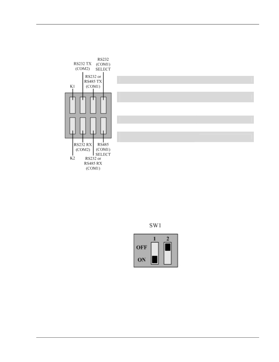
REAR PANEL INDICATORS
The rear panel of the FMS houses a series of green LEDs. The chart below tracks indicator status when the
corresponding green LED is illuminated:
Status Indicator
K1 (Output Relay)
Relay is energized.
EIA232 TX (COM2) Interface
Data is being transmitted.
EIA232 or EIA485 TX (COM1)
Interface
Data is being transmitted.
EIA232 (COM1) Select Interface EIA232
selected
(P2)
K2 (Output Relay)
Relay is energized.
EIA232 RX (COM2) Interface
Data is being received.
EIA232 or EIA485 RX (COM1)
Interface
Data is being received.
EIA485 (COM1) Select Interface EIA485
selected
(TB5)
Figure 1-2: Rear Panel Indicators
1-5
SW1 SWITCH SETTINGS
SW1-1: EIA485 Termination switch should be in the down position (ON) if the FMS is an end
device on an EIA485 network.
SW1-2: Reserved for future use.
Figure 1-3: SW1 Switch is in the down position (ON) and SW2 switch is in the up position (OFF)