Input calibration – screen version 1.47 and below – Super Systems Paperless VR User Manual
Page 38
Super Systems Inc.
Page 37 Video Recorder Manual Version 2 Rev. B
configuration menu. If the status reads False, it will not appear in the configuration menu list. Press
Save to save changes.
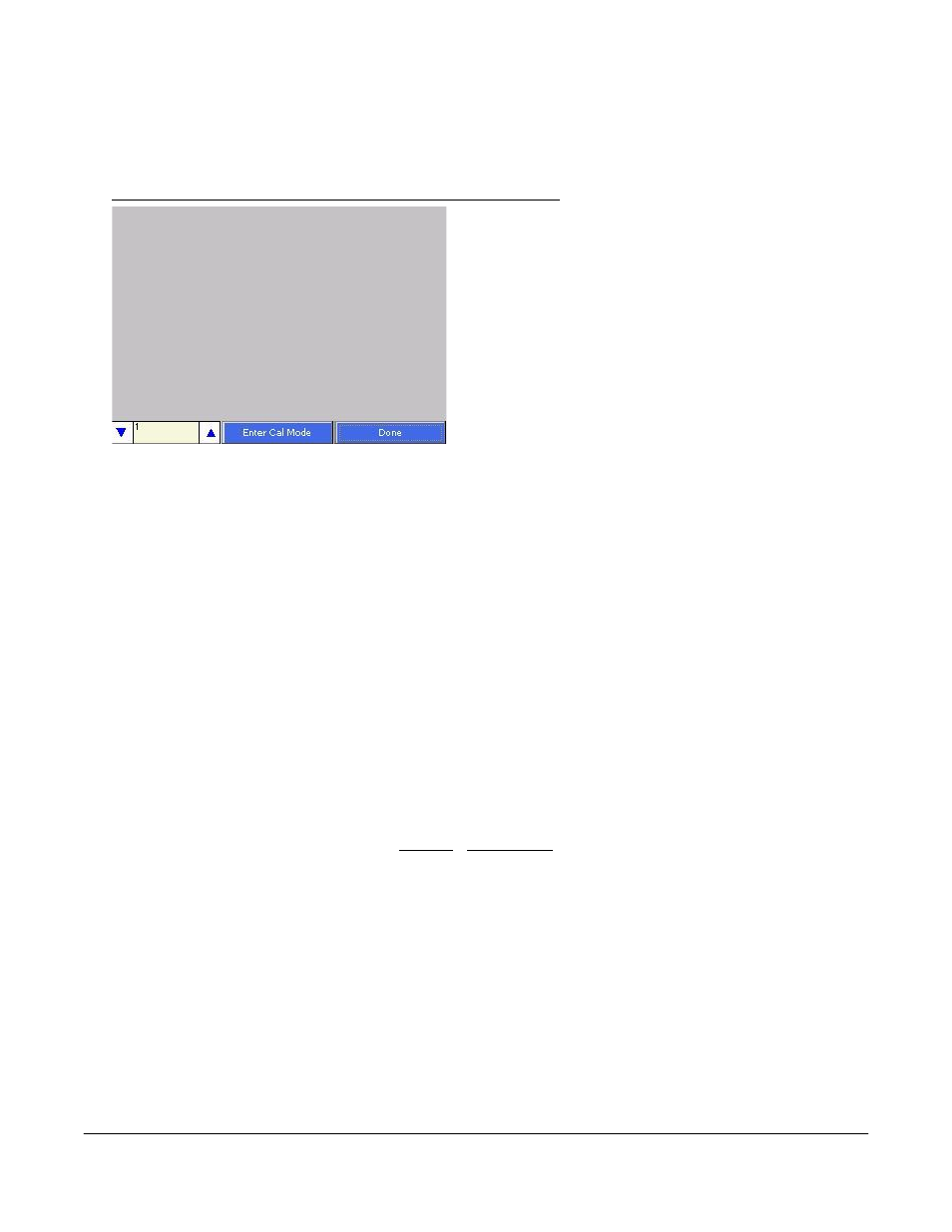
Input Calibration – Screen Version 1.47 and Below
Note: To check the screen version number, click on
the
Status
menu option from the
Configuration
menu.
The screen’s revision number will be listed next to the
“Touchscreen Revision” line
. This screen displays
information to setup the calibration of the inputs.
Calibration can be performed 1 channel at a time or
from 1 – 5 inputs per board. The user can select board
one through sixteen from the selector box on the
bottom left of the screen. Clicking on the yellow area
will display the onscreen keyboard, which will allow
the operator to enter in the number of the board to
calibrate. Once a board has been selected, press the
Enter Cal Mode button to start the calibration process.
If the module is not communicating, the software will display an error message.
The user will need a thermocouple calibrator capable of outputting a thermocouple signal to calibrate the
zero, span or cold junction value of the video recorder data logger. The user will need to connect the
calibrator to one of the inputs on the data logger for the channel that will be calibrated. It is
recommended to let everything (calibrator and datalogger) sit for approximately thirty minutes to allow
the temperature to achieve equilibrium. Set up the calibrator for the specific thermocouple type of the
thermocouples in the video recorder datalogger, i.e. type K, type J, etc. Then, source a specific
temperature, like 1000
F, or millivolt to the connected input. It is recommended that the actual
temperature used be similar to an appropriate process temperature. For example, if your equipment
normally operates at 1700
F, then perform the cold junction calibration using a 1700
F signal. It is
important to note that when performing a zero or span calibration,
do not use
regular thermocouple
wiring. Instead, use any kind of regular sensor wire, or even regular copper wire. To perform the
calibrations, the user will need a calibrator that is capable of outputting volts, millivolts, and
temperature.
Below is a listing of the suggested ranges for the various TC types.
TC Type mV Range Chart
TC Type Range in mV
B
20
C
40
E
80
J
80
K
80
N
80
NNM
80