Thermocouple connections, Voltage connections, 4 – 20 ma. current loop connections – Super Systems Paperless VR User Manual
Page 7
Super Systems Inc.
Page 6 Video Recorder Manual Version 2 Rev. B
it is attached across both pins (not just one) it will not be connected.
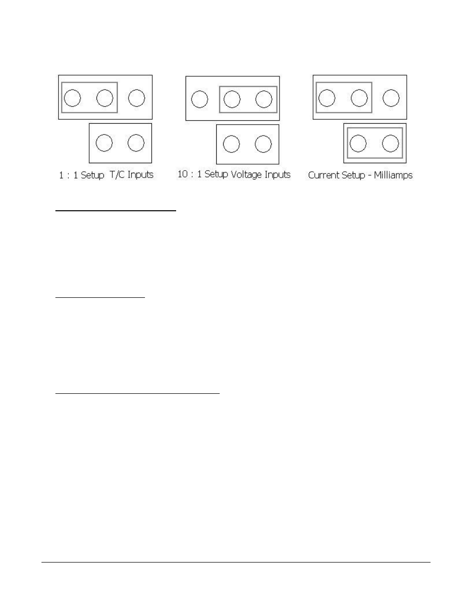
Thermocouple connections
Thermocouple wires can be connected directly to the terminal blocks. The thermocouple junctions should
not be grounded. If they do touch a ground reference, all thermocouples on a board must have a common
ground reference. If multiple thermocouples are connected to different ground reference points, the
accuracy of all thermocouples on the board cannot be guaranteed to be accurate. When setting up a
voltage input signal, such as a thermocouple input or any voltage input signal up to 1.28 volts, the jumper
must be placed on the pins in the 1:1 setup (left diagram).
Voltage connections
Voltages from 0 mV to 10 Volts DC can be directly connected to the terminal blocks. When measuring
ground-referenced voltages, all references must share a common ground reference. If the voltage
sources are connected to different ground reference points, the accuracy of all the voltage sources
connected to the board need to be checked for accuracy. Since higher voltages can damage the input
board, any voltage input signals, such as a vacuum gauge, must have the jumpers placed on the pins in
the 10:1 setup (middle diagram). This will insure that any signal going into the board will be scaled down
so it will not damage the input board.
4 – 20 mA. Current Loop connections
Before connecting the current loop, insert the shorting jumper on the board for each channel used to
measure current loops. This jumper inserts the 62-ohm shunt resistor across the input of the A/D. If
multiple current loops are connected to one board, all must share the same power supply and ground
reference points or the accuracy of all the current loops need to be checked for accuracy. When setting
up a current input signal, such as a 4 – 20 mA signal, the jumper must be placed on the pins in the
current setup (right diagram). Notice that there is also a jumper set up in the 1:1 setup only when
inputting a current signal. This is because current signals also have a corresponding voltage signal.
Warning: Connecting a mA input without the Input Jumper will damage the
input.
1. To add a jumper to an input:
2. Power down the unit.
3. Remove the thermocouple connector and the Ethernet cable from the video recorder.
4. Remove the top plate of the video recorder by unscrewing the six (6) screws around the top of the
video recorder.