Software installation, Calibration, Components – Super Systems Paperless VR User Manual
Page 5
Super Systems Inc.
Page 4 Video Recorder Manual Version 2 Rev. B
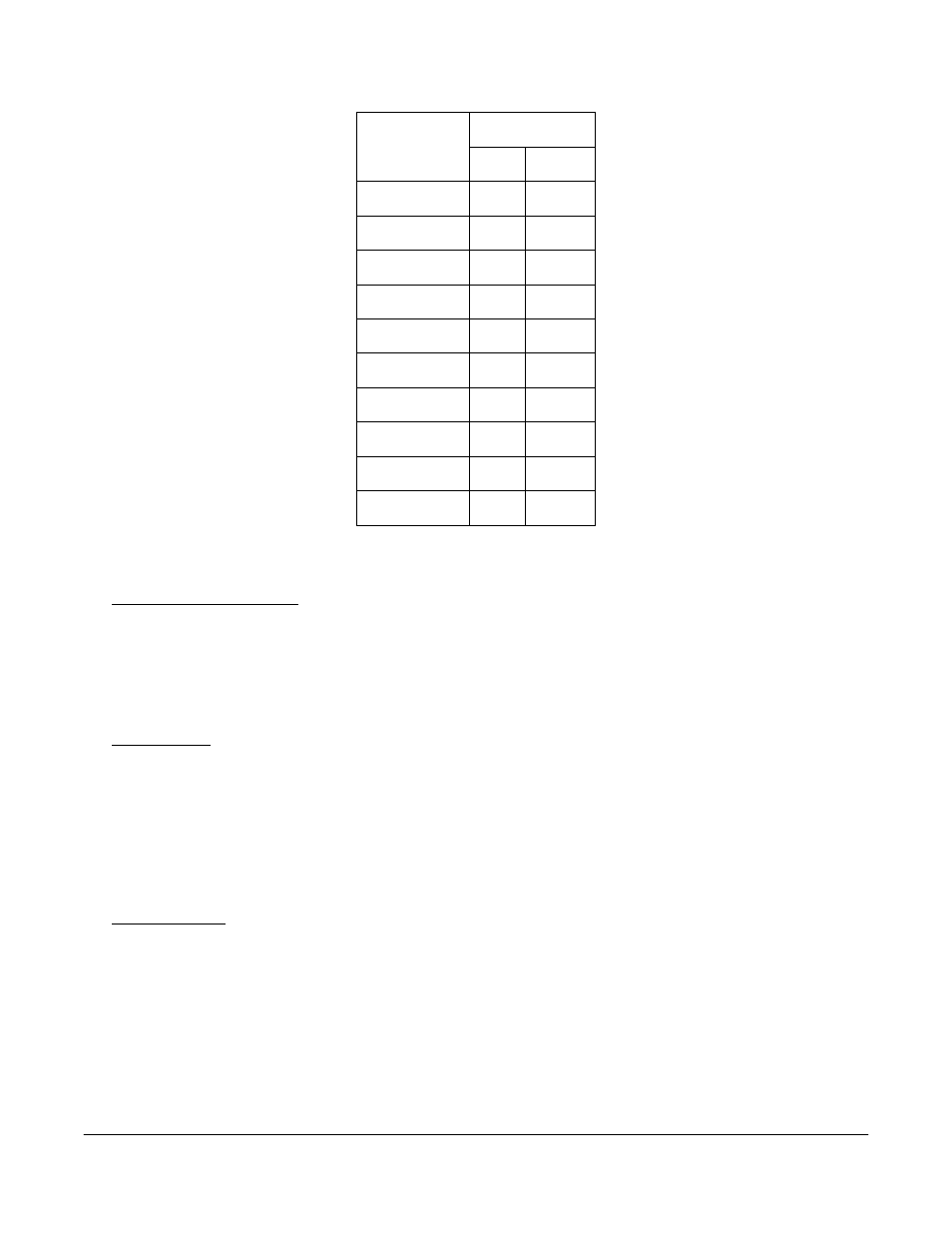
Degrees F.
TC Type
Min
Max
B
32
3308
C
32
4208
E
-328
1832
J
-346
2192
K
-328
2502
N
-328
2372
NNM
0
1409
R
-58
3214
S
-58
3214
T
-328
752
Thermocouple range listed by thermocouple
Software Installation
You will find the VR Manager software CD that ships with the unit includes all the reporting and data
management utilities. Insert the CD into the CD ROM device on your computer and click the setup.exe
file. You will be given step-by-step instructions for completing the installation process. See the section
Installing the VR Manager Software
for more details.
Calibration
The Video Recorder is calibrated prior to shipment, although the calibration process is also available
through the touch screen. Instructions for calibration are included in this manual. Super Systems
calibrates the Video Recorder using NIST traceable instruments that are listed on the calibration
certificate included with the device. The default calibration is performed using a zero and span routine
for the millivolt range of 0 – 80mV. Each range that is being used should be calibrated. For a list of
suggested mV ranges by thermocouple types, please refer to the
Input Calibration
section of this manual.
Components
The Video Recorder consists of the Touch Screen Interface, Data Logging Device, and VR Manager
Software. The Data Logging device is made up of five user-defined analog inputs per boards. Each input
is configurable using the Touch Screen Interface and allows for different math functions to be performed
on the input. Each input is fully isolated.