Setting the dip switches to assign board numbers, Getting started – Super Systems Paperless VR User Manual
Page 8
Super Systems Inc.
Page 7 Video Recorder Manual Version 2 Rev. B
5. Grasping both sides of the input board, carefully pull the input board out of the video recorder and set
the jumper for the appropriate set of pins, i.e. “V1” for input 1, “V2” for input 2, etc.
A jumper will need
to be set – placed on both pins – to be considered “on”. Slide the input board back into the video
recorder slot.
6. Replace the top plate of the video recorder by screwing in the six (6) screws around the top of the
video recorder.
7. Re-connect the Ethernet cable and thermocouple connector.
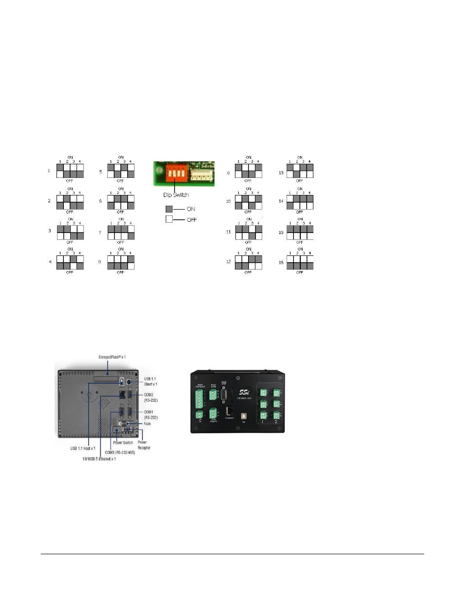
Setting the DIP switches to Assign Board Numbers
Each input board, whether
directly connected in the
Video Recorder or
connected through a
satellite box, must have a
unique address assigned
by the DIP switches on
each input board. A
unique address will
ensure that the Video
Recorder will correctly
read all of the boards set
up. If two or more boards
have the same address,
multiple errors could occur such as: VR reading data from one board one second, then reading data from
another board the next second, no data being read from the VR, etc.
It is important that each board has a
unique address
. Each DIP switch has four switches on it labeled: 1, 2, 3, and 4. These numbers follow a
binary numbering system – i.e. 1 = 1, 2 = 2, 3 = 4, and 4 = 8. There is an ON and an OFF position for each
switch. OFF = 0 and ON = 1. Each board number can be assigned by setting the appropriate switches to
ON. For example, to set a board number to 1, set the “1” switch to ON and the “2”, “3”, and “4” switches
to OFF ((1*1) + (2*0) + (4*0) + (8*0) = 1). To set the board number to 10, set the “1” and “3” switches to
OFF and the “2” and “4” switches to ON ((1*0) + (2*1) + (4*0) + (8*1) = 10).
The exception to the rule is
setting a board number to 16 – all
switches are off
.
Getting Started
The data logging device and the
touch screen have a unique IP
address. The communications
between the screen and the data
logger is performed through the
Ethernet ports. Both the screen
and data logger require separate and unique fixed IP addresses.