Grass Valley Maestro Master Control v.1.7 User Manual
Page 161
Maestro Channel Branding User Guide
157
5th Step: Input/Output Sets
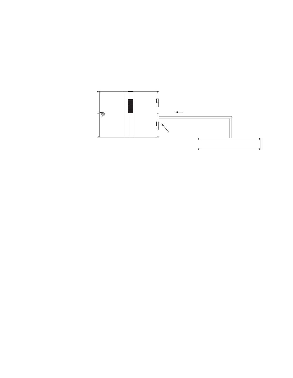
Maestro Controlled By or Controlling An External Device
The GPIO connector on the Maestro rear panel can be used to receive an
“Action: Transition” signal from a controlling external device (
),
or to transmit an “Action: Transition in Progress” signal to a controlled
external device (
).
Figure 119. GPI Connections to External Controlling Device
When used to control an external device, Maestro systems require installa-
tion of a leakage-current swamping resistor in the GPO circuit. This resistor
is used to prevent leakage current from reaching the external device when
the Maestro photocoupler relay is open. The resistor is always placed
across the input relay of the external device.
and
show examples of connections to controlled
external devices containing a small mechanical or solid-state relay, along
with a suggested location and value for the swamping resistor. A supply
voltage greater than +5 V can be used (up to + 10 V), but in that case the
power rating of the resistor would need to be increased accordingly.
TTL
Trigger
Port
Maestro
GPI Port/Photocoupler
See Notes
1A
1B
Note 1
Connections between Maestro
GPIO Connector and controlling
external device are bipolar.
Note 2
Maximum current through Maestro photocoupler = 4.25 mA
"High" range for photocoupler = 3-10 V
"Transition" signal
Controlling external device