Grass Valley Maestro Master Control v.1.7 User Manual
Page 163
Maestro Channel Branding User Guide
159
5th Step: Input/Output Sets
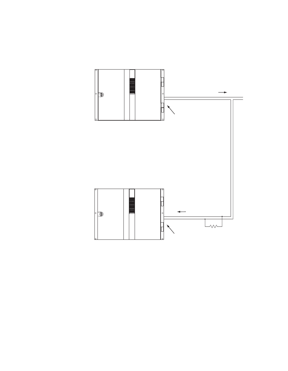
It is also possible for one Maestro processor to control another. See
.
Figure 122. Maestro-to-Maestro GPIO Connections
Note
Although the diagram above depicts two separate Maestro frames, the con-
trolling and controlled Maestro processor may be located in the same frame
The controlling Maestro would be configured to send a “Transition in Prog-
ress” signal (that is, by closing a GPO port relay) to indicate that the
Maestro has initiated a Take.
The controlled Maestro would be configured to accept a “Transition” signal
and respond by executing a Take command.
Controlling Maestro
GPO Port/Relay
See Notes
1A
1B
Note 1
Connections between Maestro
GPIO Connector and controlled
external device are bipolar.
Note 2
Maximum current through Maestro relay = 250 mA
Maximum voltage for relay = 10 V
"Transition in Progress" signal
Controlled Maestro
GPI Port/Photocoupler
See Notes
1A
1B
Note 3
Maximum current through Maestro photocoupler = 4.25 mA
"High" range for photocoupler = 3-10 V
"Transition" signal
220 ohm
1/8 W
resistor
+
-
5 V
External
power