2 rf signal conversion, 3 monitor & control – Comtech EF Data DT-4500-A Series User Manual
Page 28
DT-4500A Series Downconverters
Revision 1
Introduction
MN-DT4500A
1–4
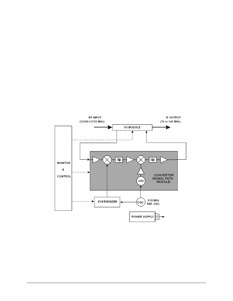
1.2.2 RF Signal Conversion
As a typical example of the RF signal processing, the RF input to the DT-4512-A Downconverter
is 12200 to 12750 MHZ at a typical level of -45 dBm. The RF is mixed in the first mixer with a
13280 to 13830 MHZ synthesizer signal from a multiplier, in 125 KHz fine tuning steps. The
synthesizer is locked to a 5/10 MHZ reference oscillator. The first mixer is located in the
downconverter Signal Path Module, and the synthesizer consists of a Coarse/Fine Step Module
and a Sum Loop Module.
The intermediate IF is 1080 MHZ which is mixed in the second mixer with the1150 MHZ IFLO
providing a +20 dBm, at 1 dB compression, 70 MHZ IF output. The second mixer is also located in
the downconverter Signal Path Assembly.
Figure 1-6 depicts the operational schematic for a typical DT-4500-A Series Downconverter in
single thread (standalone) applications. For more information about the DT-4500-A’s use in
redundant applications, refer to Appendix B. REDUNDANT SYSTEM OPERATION.
Figure 1-3. Typical Functional Block Diagram (DT-4512-A shown)
1.2.3 Monitor & Control
The Monitor & Control Assembly is designed to monitor the functions of the downconverter,
and provide the control for remote and local command inputs to the downconverter.