3 downconverter physical features, 1 front panel, 2 rear panel – Comtech EF Data DT-4500-A Series User Manual
Page 31
DT-4500A Series Downconverters
Revision 1
Introduction
MN-DT4500A
1–7
1.3.3 Downconverter Physical Features
1.3.3.1
Front Panel
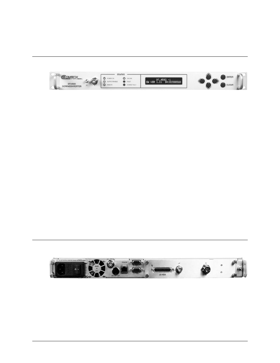
Figure 1-5. DT-4500-A Series Downconverter Front Panel
Figure 1-4 shows the typical front panel of the DT-4500-A Series Downconverters. This example
depicts the DT-4503-A Downconverter. All operator controls, indicators and displays for local
and remote operation are located on the front panel of the DT-4500-A. The front panel features
(from left):
•
Two Test Point Sample Ports – The test point connections are used for monitoring the
RF input and the IF output. An SMA connector provides the RF input, and a BNC
connector provides the IF output. There is also an optional RF LO monitor available that
replaces the RF monitor.
•
Six Light-Emitting Diode (LED) Indicators – The LEDs indicate, in a summary fashion, the
status of the unit.
•
Vacuum Fluorescent Display (VFD) – The VFD is an active display showing two lines of
24 characters each. Each configuration function, or operating mode, is shown on the
display when the operator enters a command using the keypad.
•
Six-button Keypad – The keypad comprises six individual keyswitches. They have a
positive ‘click’ action, which provides tactile feedback.
1.3.3.2
Rear Panel
Figure 1-6. DT-4500-A Series Downconverter Rear Panel
Figure 1-5 shows the typical rear panel of the DT-4500-A Series Downconverters. This example
depicts a DT-4503-A Downconverter with the Input/Output Module, or IOM, installed. The rear
panel features (from left):