Powermax, Component replacement 6-20, Service manual – Hypertherm Powermax65 Service Manual Rev.1 User Manual
Page 202
Advertising
Component ReplaCement
6-20
powermax
65/85
Service Manual
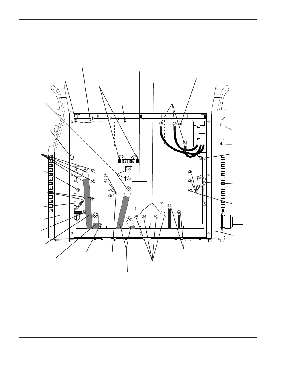
380/400V CE Power Board
WORK
LEAD
J13
J2
J1
J18
J19
J27
J30
J23
J24
TP13
J29
TP11
TP12
J7, J6, J5, J4, and J3
Gate drive
connectors
AC input wires
MOV sub-
assembly
Heat sink
mounting
screw
Heat sink
mounting
screw
Pilot arc IGBT
screws (2)
PFC inductor wires
Capacitor screws
Board
mounting
screw
Board
mounting
screw
Board
mounting
screw
Input bridge
screws (5)
Transformer wires
Output inductor wire
Electrode wire
Board
mounting
screw
Work lead
3uF Capacitor
Viewing holes
Snubber
resistor
screws (4)
Diode
screws (4)
Nozzle wire
Inverter
IGBT
screws (3)
Heat sink
mounting screw
(located behind
edge of front
panel)
Front panel
Rear panel
Advertising
This manual is related to the following products: