Powermax, Component replacement, Service manual 6-23 – Hypertherm Powermax65 Service Manual Rev.1 User Manual
Page 205
Component ReplaCement
powermax
65/85
Service Manual
6-23
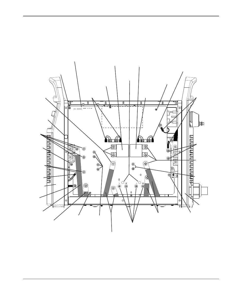
200 – 600V CSA Power Board
WORK
LEAD
BLK
BLK
J13
J16
J17
J18
J19
J26
J29
TP12
J28
TP10
TP11
J5, J4, J3, J2, and J1
Gate drive
connectors
Gate drive
connector
Heat sink
mounting
screw
Heat sink
mounting
screw
Pilot arc IGBT
screws (2)
PFC inductor wires
Capacitor
screws
Board
mounting
screw
Board
mounting
screw
Board
mounting
screw
Input bridge
screws (2)
Transformer wires
Output inductor wire
Electrode wire
Board
mounting
screw
Work lead
3uF Capacitor
3uF Capacitor
Viewing
holes
Snubber
resistor
screws (4)
Diode
screws (4)
Nozzle wire
Inverter
IGBT
screws (3)
Heat sink
mounting screw
(located behind
edge of front
end panel)
Snubber
resistor screws
(2)
Snubber
resistor wires
PFC IGBT
screws (3)
Front panel
Rear panel
PFC
temperature
sensor