Hypertherm Powermax30 AIR Service Manual User Manual
Page 125
Powermax30 AIR Service Manual 808850
125
6 – Power Supply Component Replacement
5. Place the new compressor-driver board in the power supply. Position the open slot at the bottom of the board over
the retaining screw you loosened in
step 4 on page 121. Make sure the MOSFET and diode:
Are centered on the thermal strips and are not touching the heatsink directly.
Sit evenly on the thermal strips and are not angled in any direction.
6. Install the 2 retaining screws on the left side and right side of the compressor-driver board to secure the new board
to the center panel. Tighten the screws to 17.3 kg∙cm (15 inch∙pounds).
7. Tighten the third retaining screw near the bottom of the board, just above the heatsink. Tighten the screw to
17.3 kg∙cm (15 inch∙pounds).
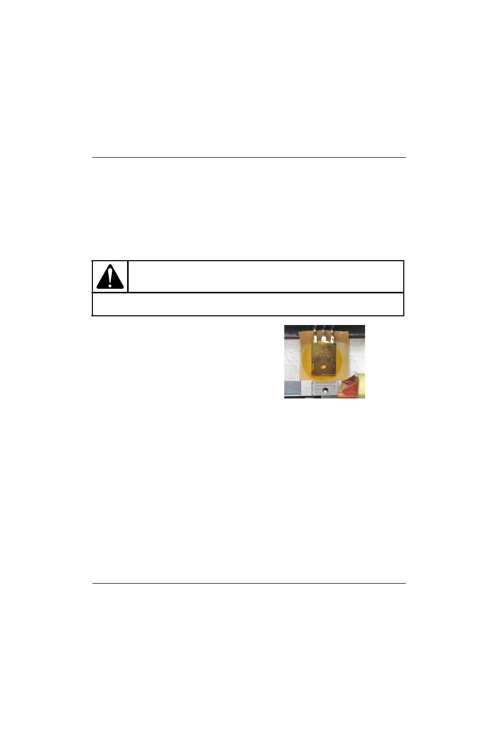
8. Peel a circular piece of polyimide tape off its backing
sheet. Adhere it evenly to the top of the MOSFET.
Make sure the tape covers the MOSFET completely.
9. Install the clips that cover the MOSFET and diode.
Tighten the screws to 17.3 kg∙cm (15 inch∙pounds).
Make sure the screw for the diode’s clip
goes straight down into the heatsink. Do not
angle the screw as you install it.
10. Reconnect the wire connectors at J1, J2, and J3 on
the compressor-driver board. See
11. Complete the following procedures:
a. See Install the component barrier on page 101.
b. See Install the power supply cover on page 99.
c. Reconnect the power cord, and set the power switch to ON (I).
CAUTION!
Do not forget to tighten the screw at the bottom of the compressor-driver board. This screw helps to
ensure the stability and reliability of the board.