Hypertherm Powermax30 AIR Service Manual User Manual
Page 75
Advertising
Powermax30 AIR Service Manual 808850
75
5 – Troubleshooting and System Tests
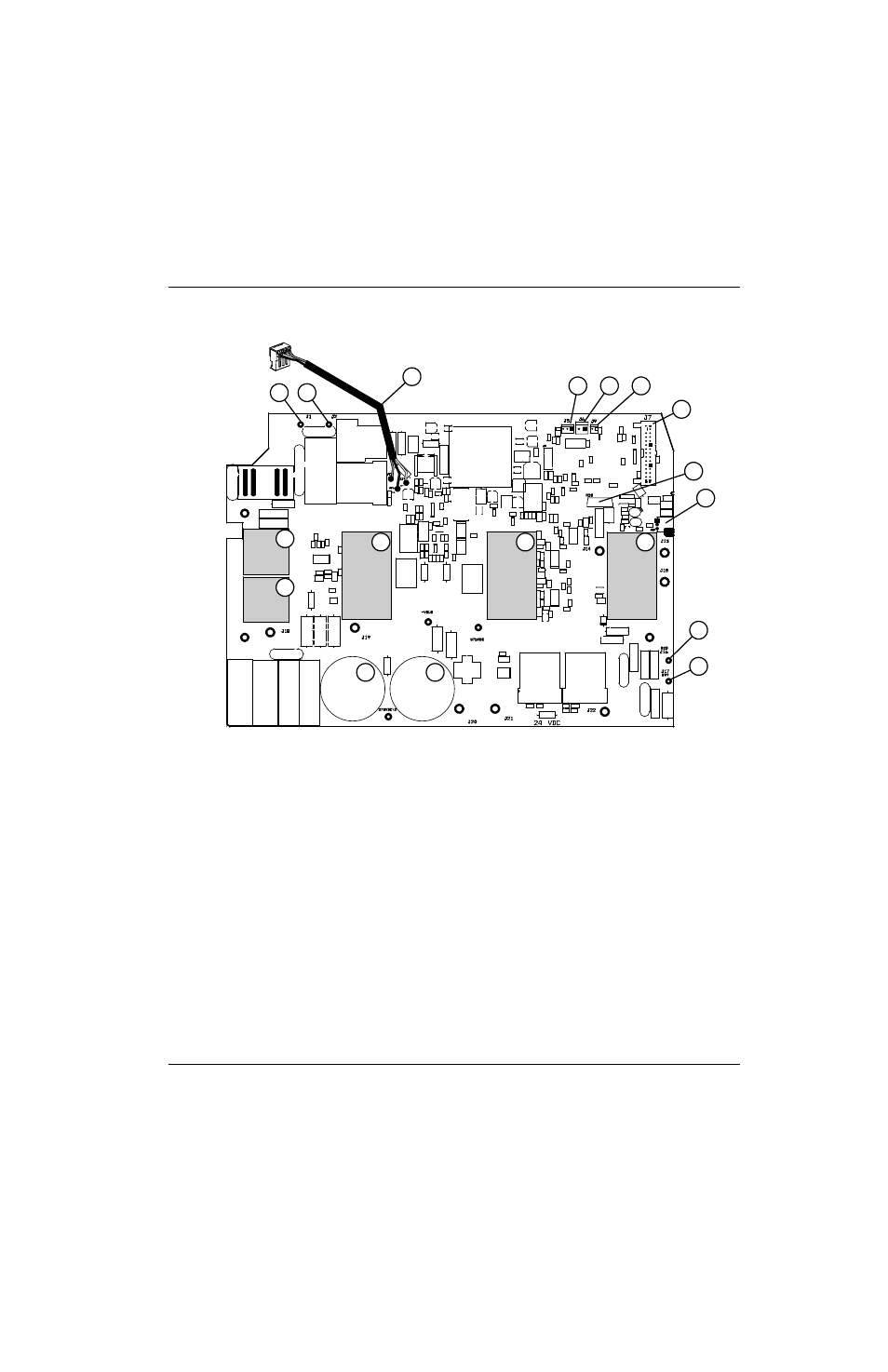
Figure 7 – Component side of the power board
1
2
6
9
1
5
5
5
2
7
8
3
4
10
11
13
14
12
1
Input diode bridges
2
Capacitors
3
J17 (white)
4
J16 (red)
5
IGBTs
6
J12 (torch-start, cap-sensor switch connector)
7
Snubber resistor
8
Ribbon cable connector (J7) from control board
9
J9
10
J6
11
J5
12
375 VDC bus voltage to compressor-driver board
13
J2
14
J1
Advertising
This manual is related to the following products: