Power supply overview, 5 – troubleshooting and system tests, Figure 2 – power board side of power supply – Hypertherm Powermax30 AIR Service Manual User Manual
Page 62
Advertising
62
Powermax30 AIR Service Manual 808850
5 – Troubleshooting and System Tests
Power supply overview
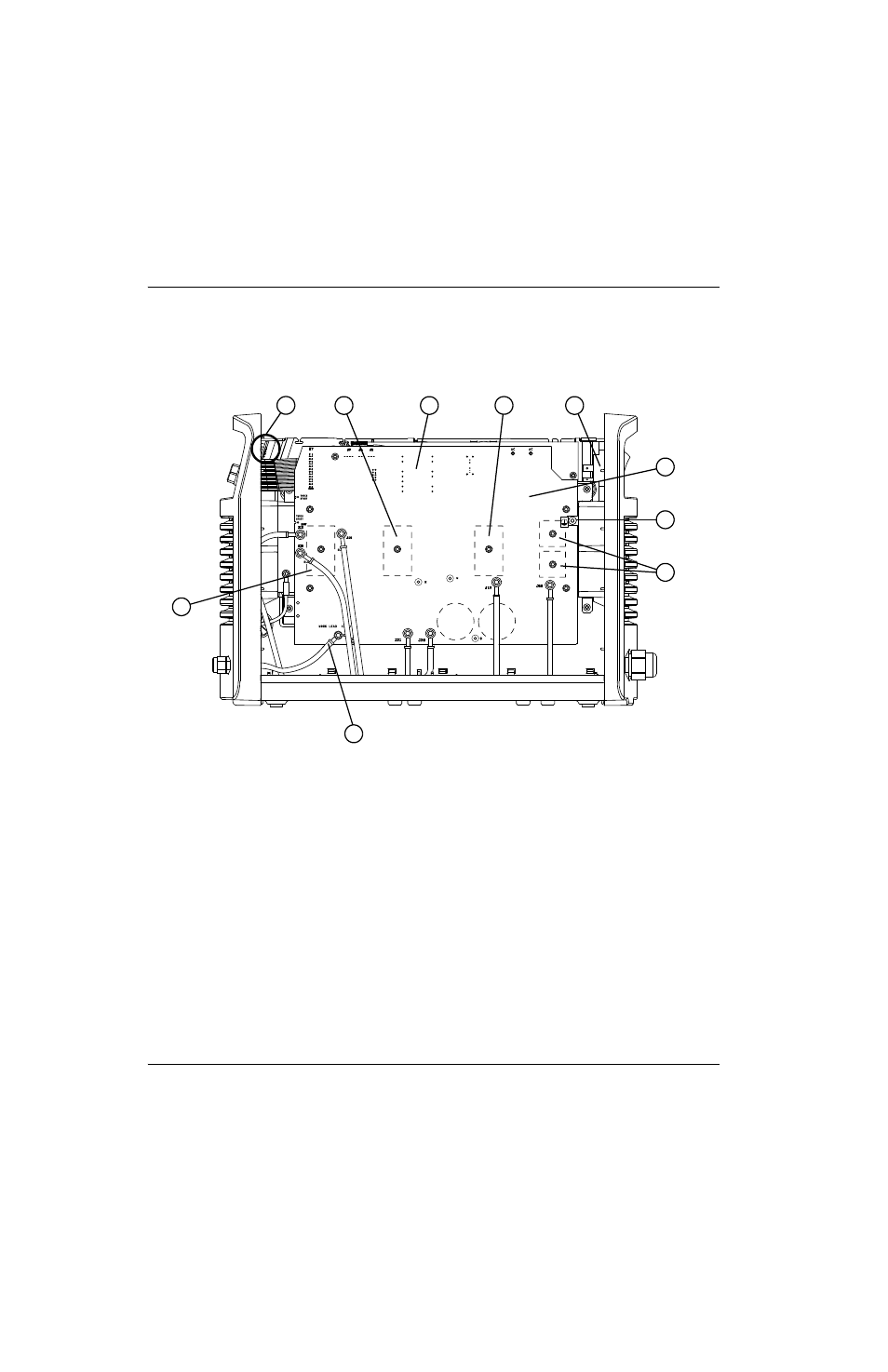
Figure 2 – Power board side of power supply
WORK LEAD (BLK)
AC
AC
R
w
TORCH
START
BLK
BLK
B
TORCH
START
1
2
4
5
6
7
8
9
10
3
1
Output diode and pilot arc IGBT module (D27)
2
Work lead connection (J22)
3
Input diode bridges (D24, D30)
4
PE (ground)
5
Power board (PCB2)
6
Power switch (S1)
7
PFC IGBT (Q1)
8
Flyback circuit
9
Inverter IGBT (Q2)
10
Control board (PCB1)
Advertising
This manual is related to the following products: