He compressor-driver board. see, Figure 20 on – Hypertherm Powermax30 AIR Service Manual User Manual
Page 94
94
Powermax30 AIR Service Manual 808850
5 – Troubleshooting and System Tests
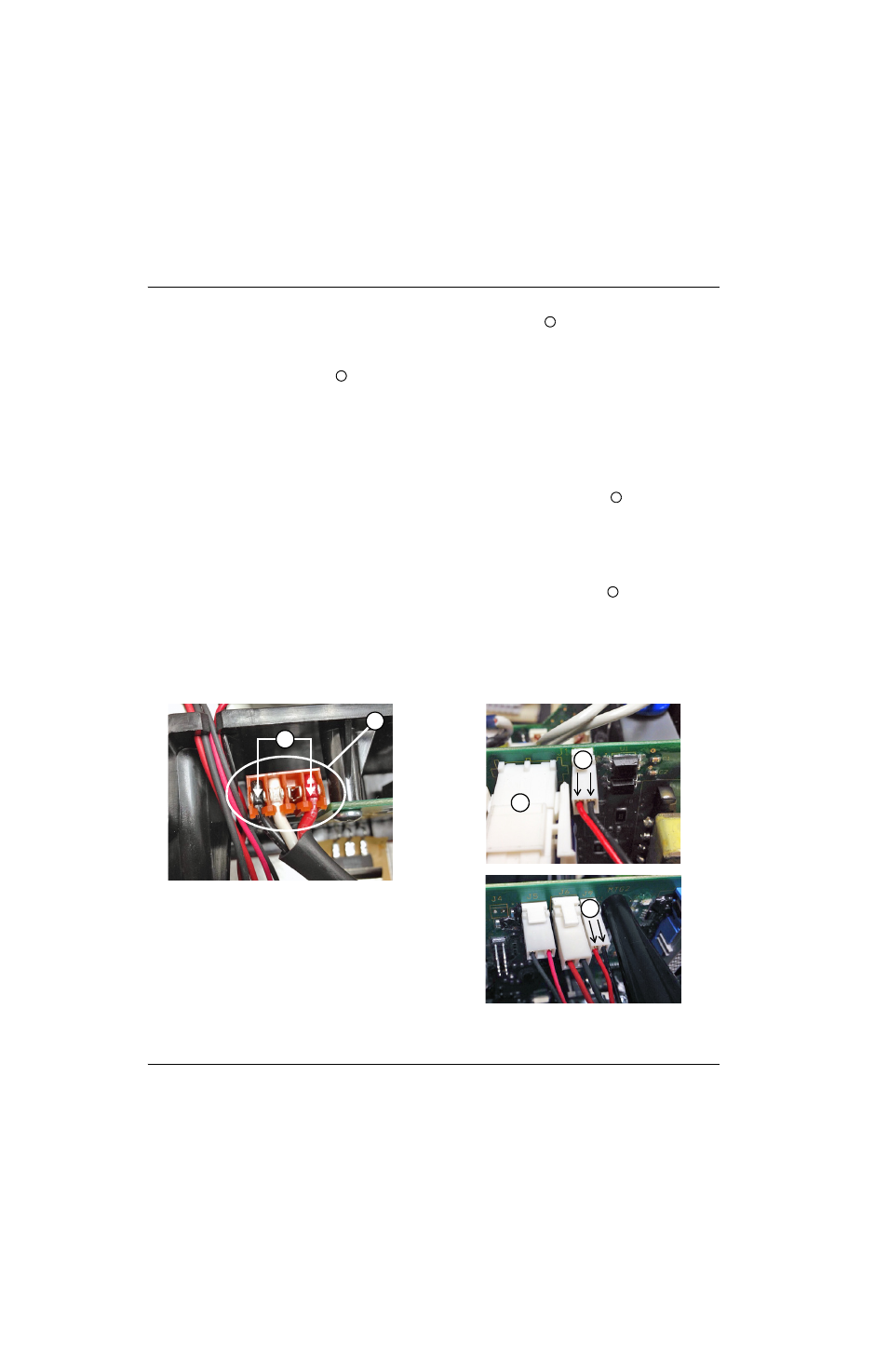
18. Check VBUS on the red and black wires on the J3 connector (pin 1 and pin 4)
. Is VBUS present (nominal
375 VDC bus voltage)?
a. If yes, check the compressor-enable voltage on the compressor-driver board. Skip to step 20.
b. If no, remove the J2 connector
from the compressor-driver board. Continue with the next step.
19. Repeat the previous step to check VBUS with J2 disconnected. Is VBUS present (nominal 375 VDC bus voltage)?
a. If yes, check the compressor-enable voltage on the compressor-driver board. Continue with the next step.
b. If no, check the power board. Skip to step 23.
20. Set the power switch to ON (I).
21. Quickly tap the torch trigger, then check the compressor-enable voltage on the J1 connector
on the
compressor-driver board. Is compressor-enable voltage present (3 VDC)?
a. If yes, replace the compressor-driver board. See Replace the compressor-driver board on page 121.
b. If no, check the twisted pair wires that connect the compressor-driver board to the power board. Continue with
the next step.
22. Quickly tap the torch trigger, then check the compressor-enable voltage on the J9 connector
on the power board.
Is compressor-enable voltage present (3 VDC)?
a. If yes, replace the J1-to-J9 twisted pair wires. See Replace the wire group on page 137.
b. If no, check the power board. Continue with the next step.
Figure 20
6
7
8
9
5
6
7
8
9