Check the power switch – Hypertherm Powermax30 AIR Service Manual User Manual
Page 60
60
Powermax30 AIR Service Manual 808850
5 – Troubleshooting and System Tests
Check the power switch
1. Set the power switch to OFF (O), disconnect the power cord from the power source, and then set the power switch
to ON (I).
2. Check the resistance across the input leads.
The resistance should read as approximately
75 kΩ.
3. Check the resistance from the input leads to
ground to make sure it reads as open. For all
power supplies, the resistance from input to
ground should read as > 20 MΩ.
With the electrical power disconnected
and the power switch set to OFF (O), all
circuits should read as open.
The electrical value shown is ±25%.
However, this range is intended only for
reference. Resistance values can vary
widely depending on the type of
multimeter and the polarity used to
measure the readings.
4. Remove the consumables from the torch.
If you do not remove the consumables, the
resistance values will not read correctly.
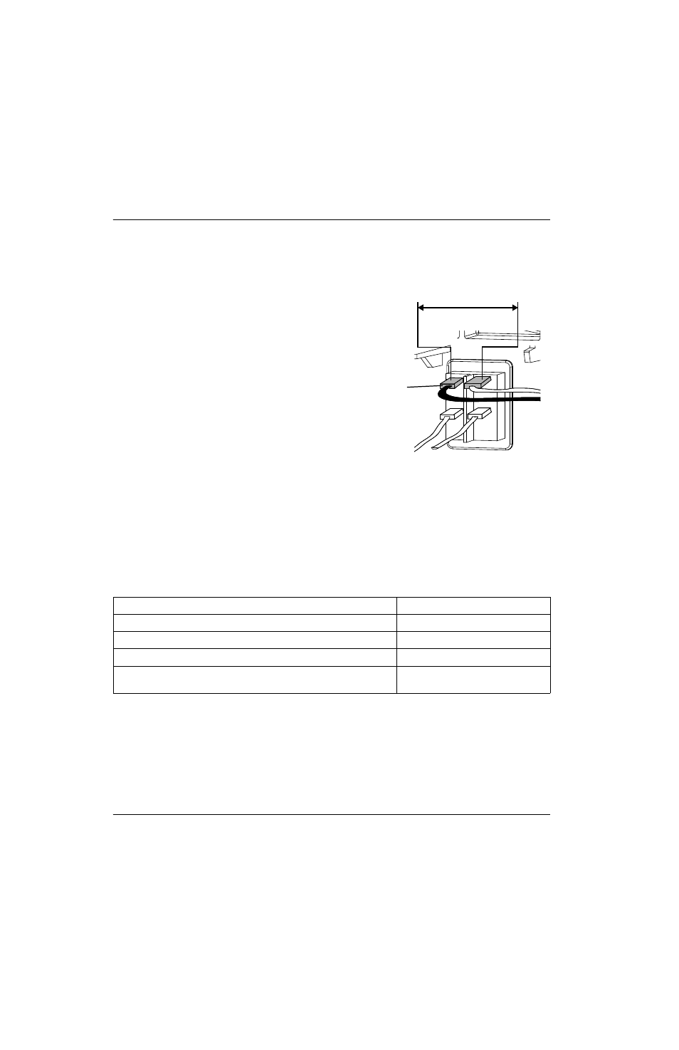
5. Check the output resistance for the values shown in the following table.
J16 and J17 are labeled on the component side of the power board. See
locations on the back side of the power board.
Measure resistance from (with consumables removed)
Approximate values
Work lead (J22) to nozzle (J16, red wire)
100 kΩ
Work lead (J22) to electrode (J17, white wire)
20 kΩ
Electrode (J17, white wire) to nozzle (J16, red wire)
120 kΩ
Work lead (J22), nozzle (J16, red wire), and electrode (J17, white wire) to
ground
> 20 MΩ
75 kΩ
Black (CSA)
Brown (CE)