Figure d–3 – Altera Cyclone II DSP Development Board User Manual
Page 111
Altera Corporation
Reference Manual
D–3
August 2006
Cyclone II DSP Development Board
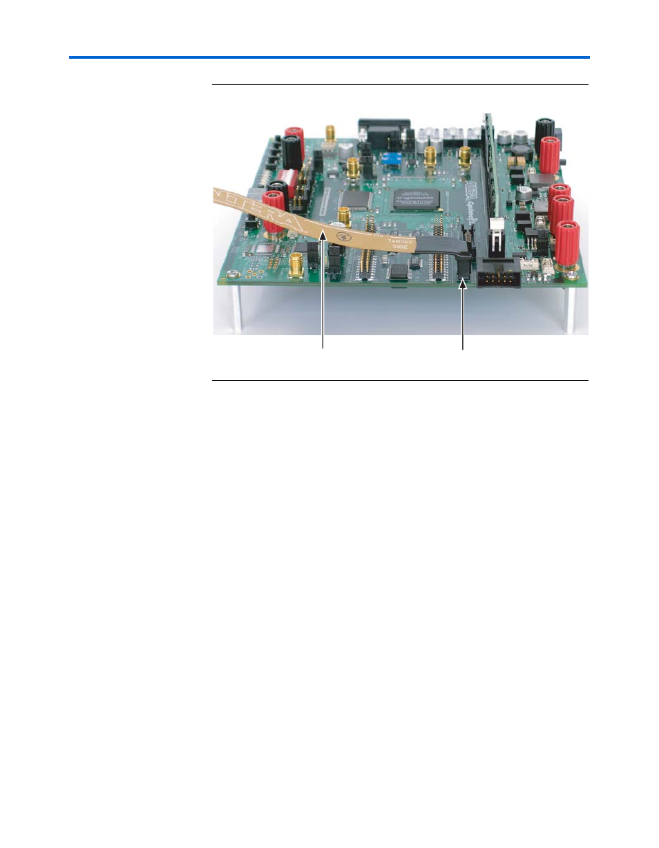
Figure D–3. The JTAG Cable Connected to the ASI Connector J13
3.
Run the Quartus II software
4.
Select Programmer (Tools menu).
5.
In the Mode box, select Active Serial Programming, click Add File.
6.
Browse to the directory:
<install-path>\CycloneII_DSP_Kit-v6.0.1\Examples\
FactoryDesign_ChA
.
f
Software and hardware installation and setup are described in the DSP
Development Kit, Cyclone II Edition Getting Started User Guide.
7.
Select sines.pof and click Open.
8.
Turn on Program/Configure and click Start to program the EPCS64.
When the Progress bar reaches 100%, programing is complete.
9.
Press SYS RESET (SW7) to reset the hardware and reconfigure the
Cyclone II DSP development board in SYS RESET mode. You should
see the POWER LED (D1) turn on, indicating power is present, the
LEDs D2 through D5 (USER_LED0 through USER_LED4,
J13
ASI Connector
JTAG Cable