User-defined leds (d2 through d9) – Altera Cyclone II DSP Development Board User Manual
Page 18
Advertising
2–10
Reference Manual
Altera Corporation
Cyclone II DSP Development Board
August 2006
User Interfaces
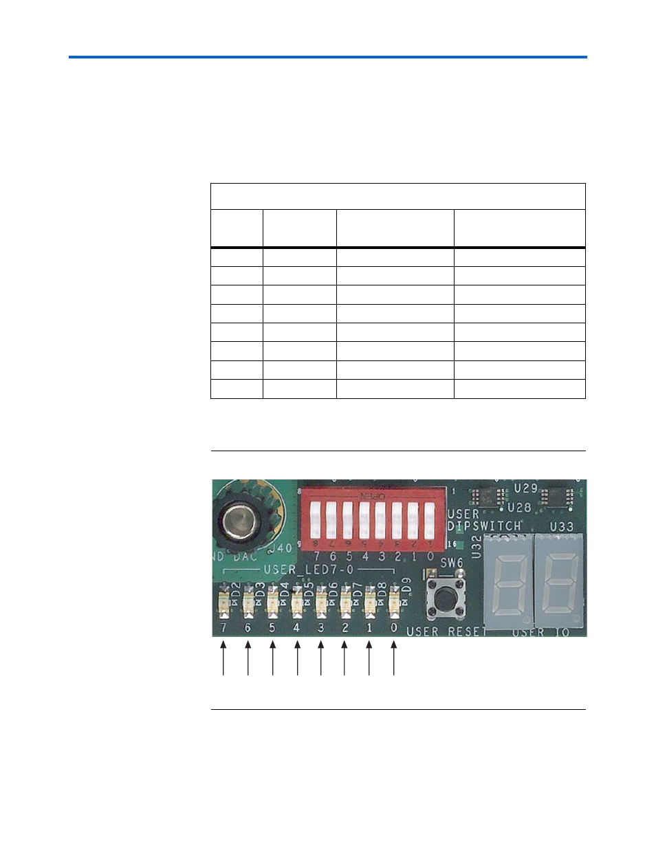
User-Defined LEDs (D2 Through D9)
The Cyclone II DSP development board provides eight user-defined
LEDs. D2 through D9 are connected to general purpose I/O pins on the
EP2C70 FPGA as listed in
. When the EP2C70 FPGA drives logic
0, the corresponding LED turns on.
shows the user-defined LEDs.
Figure 2–3. User-Defined LED0 Through LED7
Table 2–3. User-Defined LED Pin-Outs
LED
Number
Board
Reference
Schematic Signal
Name
Cyclone II (U12) Pin
Number
7
D2
USER_LED7
AA7
6
D3
USER_LED6
AA6
5
D4
USER_LED5
AB4
4
D5
USER_LED4
AC3
3
D6
USER_LED3
E22
2
D7
USER_LED2
F20
1
D8
USER_LED1
B3
0
D9
USER_LED0
E5
7
D2
6
D3
5
D4
4
D5
3
D6
2
D7
1
D8
0
D9
Advertising