D/a converter power select jumper (j33), Clock buffer (u16), On-board clock oscillator (u20) – Altera Cyclone II DSP Development Board User Manual
Page 71
Altera Corporation
Reference Manual
2–63
August 2006
Cyclone II DSP Development Board
Cyclone II DSP Development Board Components
D/A Converter Power Select Jumper (J33)
J33 determines whether the D/A converter is powered at 3.3 volts or 5
volts. When the jumper is on pins 2 and 3, the D/A converter is powered
at 3.3 volts. When the jumper is on pins 1 and 2., the D/A converter is
powered at 5 volts.
Clock Buffer (U16)
U16 generates the clocks used on the Cyclone II DSP development board.
U16 generates seven identical clock outputs that carry clock signals to
other components on the Cyclone II DSP development board. The clock
buffer is a low-skew, single-input to eight-output clock buffer (one output
is unconnected and two outputs are unused).
lists the U16 pin-
outs.
On-Board Clock Oscillator (U20)
The on-board clock oscillator is a 100-MHz free-running oscillator that
can be used as an input to U16.
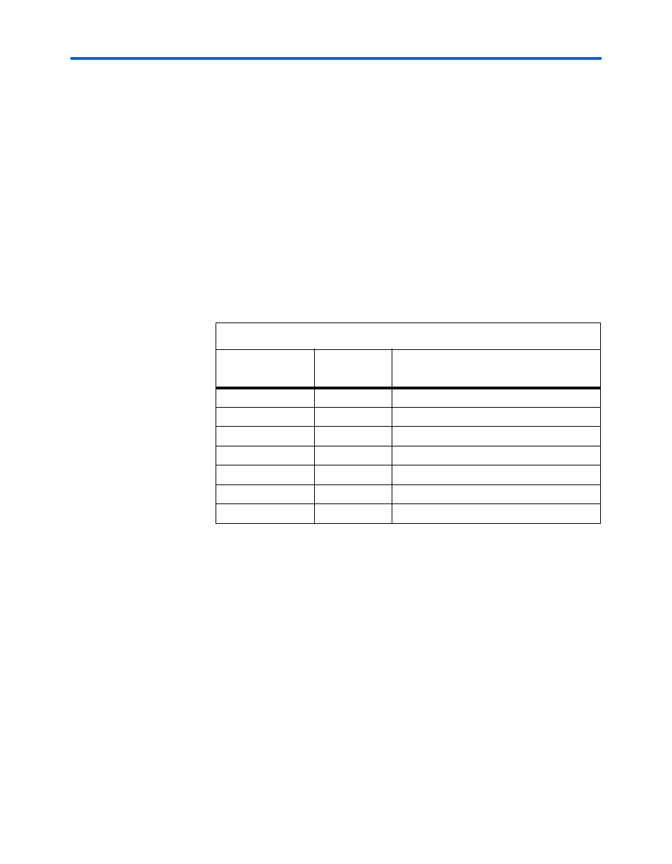
Table 2–32. Clock Buffer Distribution
Clock Buffer
Output Pin (U16)
Destination
Description
U16.3
U12.N2
Cyclone II
U16.4
U12.N25
Cyclone II
U16.5
J23.9
Expansion Prototype Connector
U16.11
J37.1
A/D converter Channel A Clock Select
U16.13
J35.1
D/A CONVERTER Channel A Clock Select
U16.12
J36.1
A/D converter Channel B Clock Select
U16.14
J34.1
D/A CONVERTER Channel B Clock Select