Altera Cyclone II DSP Development Board User Manual
Page 62
2–54
Reference Manual
Altera Corporation
Cyclone II DSP Development Board
August 2006
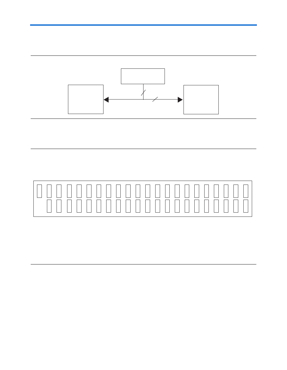
General Connectors
shows the connections from the Mictor connector to the
EP2C70 FPGA and the JTAG connector.
Figure 2–18. Mictor Connector Signaling
shows the J12 pin-outs to the EP2C70. Unless otherwise
noted, labels indicate EP2C70 pin numbers.
Figure 2–19. Mictor Connector (J12) Pin-Outs
Notes to
:
(1)
Pins 5, 6, 11, 15, 17, and 19 are not connected to the EPC335 FPGA.
(2)
Pins 12 and 14 are at 3.3V.
(3)
Pins 39 through 43 are GND.
EP2C35F672
(U12)
40
4
Mictor Connector
J12
JTAG Connector
J9
38 J5
37 D1
40 GND
(3)
39 GND
(3)
42 GND
(3)
41 GND
(3)
43 GND
(3)
36 H6
35 F1
34 G6
33 G1
32 F6
31 J3
30 L6
29 H1
28 L7
27 J1
26 K7
25 J2
24 J8
23 K1
22 G5
21 NC
20 F4
19
(1)
18 G4
17
(1)
16 G3
15
(1)
14 3.3
V
(2
)
13 L2
12 3.3
V
(2
)
11
(1)
10 C2
9 M3
8 F2
7 M2
6
(1)
5
(1)
4 NC
3 NC
2 NC
1 NC