Status leds & reset/power switches, Power (d1) & status (d10) leds, Power switch (sw1) – Altera Cyclone II DSP Development Board User Manual
Page 65: User defined reset (sw6) push-button, Featur
Altera Corporation
Reference Manual
2–57
August 2006
Cyclone II DSP Development Board
Cyclone II DSP Development Board Components
Status LEDs &
Reset/Power
Switches
This section describes the status LEDs and reset switches on the
Cyclone II DSP development board. Some of the switches are user-
defined.
Power (D1) & Status (D10) LEDs
The power LED (D1) turns on indicating that voltage is supplied to the
DC jack, J1, and is being distributed to the Cyclone II DSP development
board’s on-board power regulators. For information about powering up
the Cyclone II DSP development board, see
.
The Cyclone II DSP development board has one CONF DONE LED (D10)
that turns on to indicate successful configuration of the EP2C70 FPGA.
This LED is driven by the EP2C70(U12), pin R23 (CONF_DONE). See
Power Switch (SW1)
SW1 is a power switch that connects the 9-20 V DC input from the DC
power jack, J1, to the on-board power regulators. When SW1 is in the ON
position, LED (D1) turns on.
User Defined Reset (SW6) Push-Button
SW6 is a USER RESET momentary-contact push button. It is used as
defined by the user, and could be used for initialization and reset of a user
design running on the Cyclone II DSP development board. This button
must first be defined by the user before it can be used. See
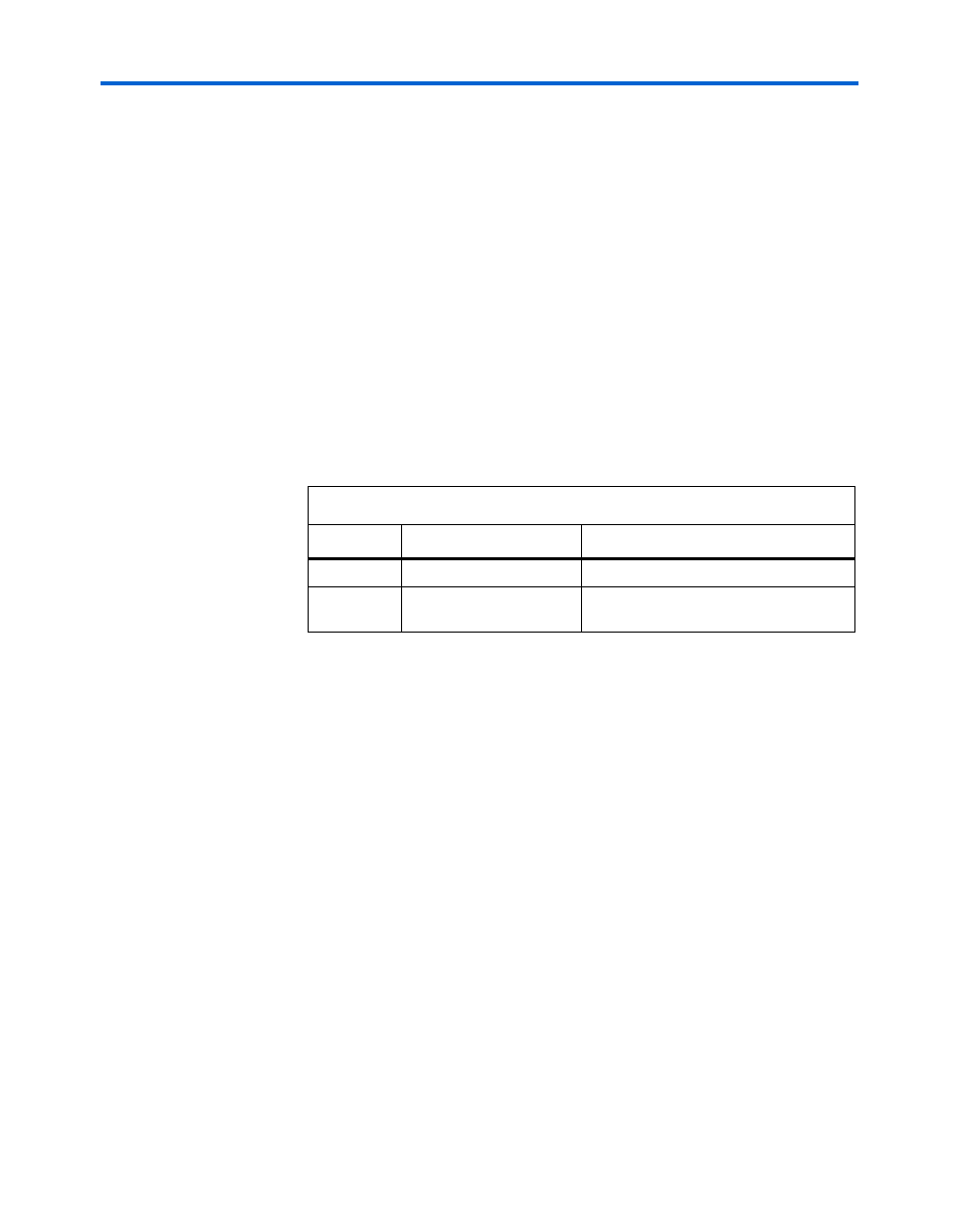
Table 2–29. Status & Power LEDs Pin-Outs
LED Name
Schematic Signal Name
Description
D1
DC_IN
DC Input Power OK
D10
EP2C_CONFIG_DONE
Cyclone II DSP development board
successfully configured