Setting the clocks – Altera Cyclone II DSP Development Board User Manual
Page 68
2–60
Reference Manual
Altera Corporation
Cyclone II DSP Development Board
August 2006
Clock Circuitry
Setting the Clocks
The clocks are selected from one of the following clock sources (as shown
in
■
The on-board clock oscillator (U20)
■
The custom clock oscillator (J20)
■
The SMA connector (J17)
The following two jumpers select the clock outputs from the clock buffer
(U16). (see
):
1.
J18 selects U20 or J20 as the selected clock oscillator to be input to
U16.
2.
J19 determines which input to U16 (the selected clock oscillator or
the SMA clock), will be used to output the clocks.
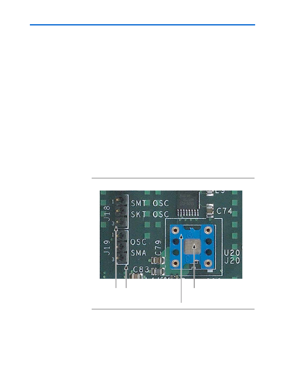
shows U20, the on-board 100 MHz clock oscillator (it is
mounted in the gray area as the arrow indicates. If a custom clock
oscillator is used, it is installed on the blue socket (J20), as the arrow
indicates, on top of U20.
also shows J18 and J19.
Figure 2–22. U20/J20, J18 & J19
J19
U20 - On-Board
100 MHz Oscillator
J18
Socket to Mount J20 - Custom Oscillator
(Mounts on Top of U20)