Terminals on the upper face – CIRCUTOR CVM-B Series User Manual
Page 12
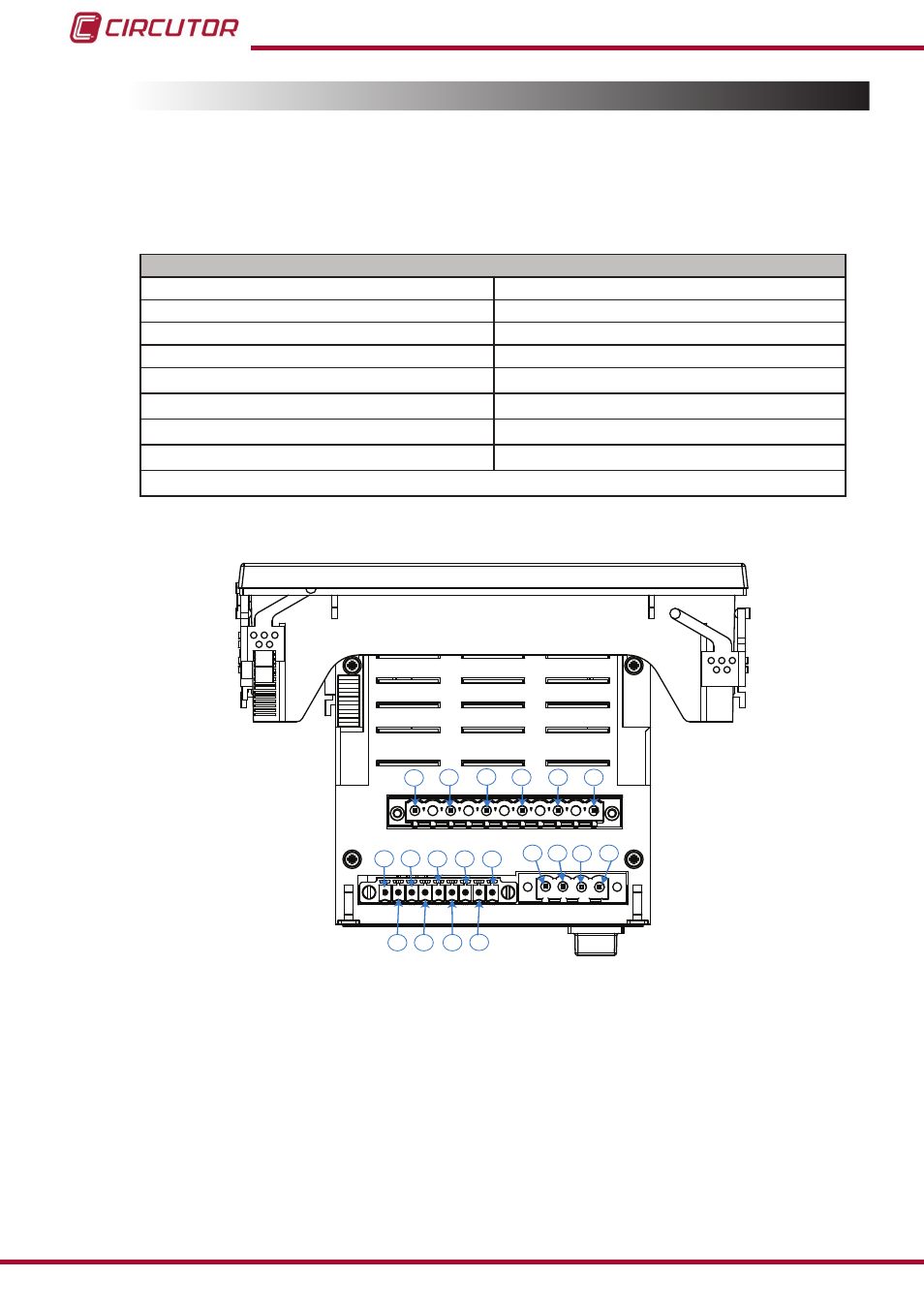
3.3.- UNIT TERMINALS
The
CVM-B terminals are distributed between the upper and lower face of the unit.
3�3�1�- Terminals on the upper face
Table 3:List of terminals on the upper face of the CVM-B�
Terminals of the top side of the unit
1: V
Ref
, Reference voltage input
10: T
1
, Digital output of transistor 1
2: N
Ref
, Reference voltage neutral
11: T
2
, Digital output of transistor 2
3: N, Voltage input neutral
12: T
C
, Common digital output of transistor
4: V
L3
,Voltage input L3
13: A(+), RS485
5: V
L2,
Voltage input L2
14: B(-), RS485
6: V
L1,
Voltage input L1
15: S, GND for RS-485
7: I
1
, Digital input 1
16, 17: R
1
, Relay digital output 1
8: I
2
, Digital input 2
18, 19: R
2
, Relay digital output 2
9: I
c
, for digital inputs
1
2
3
4
5
6
7
10
9
12
11 13
14
15
8
16 17 18 19
figure 1: CVM-Bx terminals, upper face�
12
CVM-B100 - CVM-B150
Instruction Manual