CIRCUTOR CVM-B Series User Manual
Page 224

7�2�4�5�- Status of relay digital outputs
The following functions are implemented for these variables:
function 0x04: reading registers.
function 0x10: Writing multiple registers.
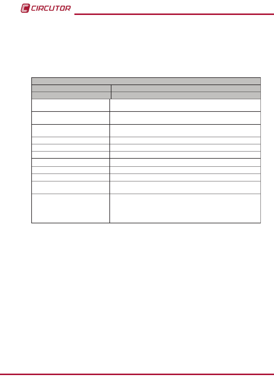
Table 78:Modbus memory map: Status of relay digital outputs (Table 1)�
Status of relay digital outputs
Configuration variable
Valid data window
Alarm
Alarm
Latch
(1)
0: unlock alarm
1: locked alarm
Connection delay
(2)
Energy meter which indicates the value of the connection delay variable
(ON)
Disconnection delay
(2)
Energy meter which indicates the value of the disconnection delay vari-
able (OFF)
Alarm activation date: Year
(2)
2013 to 2076
Alarm activation date: Month
(2)
1 to 12
Alarm activation date: Day
(2)
1 to 31
Alarm activation time: Hour
(2)
0 to 23
Alarm activation time: Minutes
(2)
0 to 59
Alarm activation time: Seconds
(2)
0 to 59
Status
(2)
0: No alarm,
1: Active alarm,
Alarm status
(2)
0: No alarm,
1: Pre-alarm,
2: Connection or disconnection delay,
3: Alarm,
4: Impulses.
(1)
If the latch option has been programmed in an alarm and it has been activated, the alarm will be unlocked with
this option.
(2)
For these variables only
function 0x04 is implemented: reading registers.
224
CVM-B100 - CVM-B150
Instruction Manual