Sition of input channels – CIRCUTOR CVM-B Series User Manual
Page 196
6�3�7�16�- User interface
These parameters occupy 1 register each.
Table 48:Modbus memory map: Configuration variables (user interface)
User interface
Configuration variable
Address
Valid data window
Default value
Sensitivity
280C
0: low, 1: medium, 2: high
1
Fade-off time
280D
1-99 (minutes)
15
Decimal display
280E
0: Decimal mark: comma.
1: Decimal mark: period
0
Date format
280F
0: dd/mm/yyyy.
1: dd/mm/yyyy.
1
6�3�7�17�- Position of input channels
This parameter occupies 1 register.
Table 49:Modbus memory map: Configuration variables (Position of input channels).
Position of input channels
Configuration variable
Address
Default value
Position of input channels
2850
0x0924
This variable allows you to switch the voltage and current channels and reverse the current
direction, enabling the correction of an incorrect installation.
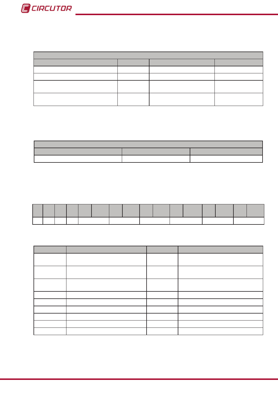
The variable format is shown in
Table 50:Variable format: Position of input channels�
Bit
15
Bit
14
Bit
13
Bit
12
Bit
11
Bit
10
Bit
9
Bit
8
Bit
7
Bit
6
Bit
5
Bit
4
Bit
3
Bit
2
Bit
1
Bit
0
I3
I2
I1
0
Channel 3 I Channel 2 I Channel 1 I Channel 3 V Channel 2 V Channel 1 V
Where:
Table 51:Variable format: Position of input channels (description)
Bit
Description
Address
Valid data window
I3
Direction of the current of L3
Bit 15
0: The direction does not change
1: Changes the direction of the current
I2
Direction of the current of L2
Bit 14
0: The direction does not change
1: Changes the direction of the current
I1
Direction of the current of L1
Bit 13
0: The direction does not change
1: Changes the direction of the current
Channel 3 I
Current channel 3
Bit 11 and 10
00: L1 , 01:L2 , 10: L3
Channel 2 I
Current channel 2
Bit 9 and 8
00: L1 , 01:L2 , 10: L3
Channel 1 I
Current channel 1
Bit 7 and 6
00: L1 , 01:L2 , 10: L3
Channel 3 V
Voltage channel 3
Bit 5 and 4
00: L1 , 01:L2 , 10: L3
Channel 2 V
Voltage channel 2
Bit 3 and 2
00: L1 , 01:L2 , 10: L3
Channel 1 V
Voltage channel 1
Bit 1 and 0
00: L1 , 01:L2 , 10: L3
196
CVM-B100 - CVM-B150
Instruction Manual