CIRCUTOR CVM-B Series User Manual
Page 237
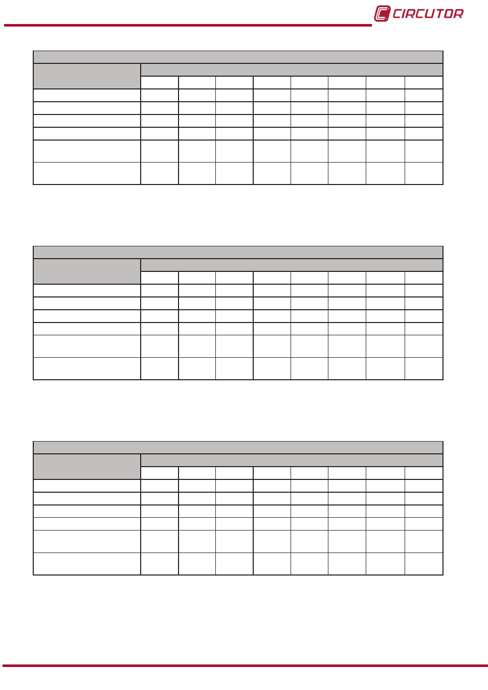
Table 97:Modbus memory map: Digital inputs, expansion modules (Table 3)�
Configuration of digital inputs: Slot 2
Configuration variable
Address
Input 1 Input 2 Input 3 Input 4 Input 5 Input 6
Input 7
Input 8
Mode
C8C8
C8D4
C8E0
C8EC
C8F8
C904
C910
C91C
Logic (Logic state)
C8C9
C8D5
C8E1
C8ED
C8F9
C905
C911
C91D
No. of decimals (Impulses)
C8CA
C8D6
C8E2
C8EE
C8FA
C906
C912
C91E
Not used
C8CB
C8D7
C8E3
C8EF
C8FB
C907
C913
C91F
Input name (impulses)
C8CC-
C8CF
C8D8-
C8DB
C8E4-
C8E7
C8F0-
C8F3
C8FC-
C8FF
C908-
C90B
C914-
C917
C920-
C923
Units (Impulses)
C8D0-
C8D2
C8DC-
C8DE
C8E8-
C8EA
C8F4-
C8F6
C900-
C902
C90C-
C90E
C918-
C91A
C924-
C926
Note: The 11 registers must be written and read at once (as a group), otherwise it will respond
with an error.
Table 98:Modbus memory map: Digital inputs, expansion modules (Table 4)�
Configuration of digital inputs: Slot 3
Configuration variable
Address
Input 1 Input 2 Input 3 Input 4 Input 5 Input 6
Input 7
Input 8
Mode
CCB0
CCBC
CCC8
CCD4
CCE0
CCEC
CCF8
CD04
Logic (Logic state)
CCB1
CCBD
CCC9
CCD5
CCE1
CCED
CCF9
CD05
No. of decimals (Impulses)
CCB2
CCBE
CCCA
CCD6
CCE2
CCEE
CCFA
CD06
Not used
CCB3
CCBF
CCCB
CCD7
CCE3
CCEF
CCFB
CD07
Input name (impulses)
CCB4 -
CCB7
CCC0 -
CCC3
CCCC -
CCCF
CCD8-
CCDB
CCE4-
CCE7
CCF0-
CCF3
CCFC-
CCFF
CD08-
CD0B
Units (Impulses)
CCB8 -
CCBA
CCC4 -
CCC6
CCD0 -
CCD2
CCDC-
CCDE
CCE8-
CCEA
CCF4-
CCF6
CD00-
CD02
CD0C-
CD0E
Note: The 11 registers must be written and read at once (as a group), otherwise it will respond
with an error.
Table 99:Modbus memory map: Digital inputs, expansion modules (Table 5)�
Configuration of digital inputs: Slot 4
Configuration variable
Address
Input 1 Input 2 Input 3 Input 4 Input 5 Input 6
Input 7
Input 8
Mode
D098
D0A4
D0B0
D0BC
D0C8
D0D4
D0E0
D0EC
Logic (Logic state)
D099
D0A5
D0B1
D0BD
D0C9
D0D5
D0E1
D0ED
No. of decimals (Impulses)
D09A
D0A6
D0B2
D0BE
D0CA
D0D6
D0E2
D0EE
Not used
D09B
D0A7
D0B3
D0BF
D0CB
D0D7
D0E3
D0EF
Input name (impulses)
D09C-
D09F
D0A8-
D0AB
D0B4-
D0B7
D0C0-
D0C3
D0CC-
D0CF
D0D8-
D0DB
D0E4-
D0E7
D0F0-
D0F3
Units (Impulses)
D0A0-
D0A2
D0AC-
D0AD
D0B8-
D0BA
D0C4-
D0C6
D0D0-
D0D2
D0DC-
D0DE
D0E8-
D0EA
D0F4-
D0F6
Note: The 11 registers must be written and read at once (as a group), otherwise it will respond
with an error.
237
Instruction Manual
CVM-B100 - CVM-B150