CIRCUTOR CVM-B Series User Manual
Page 257
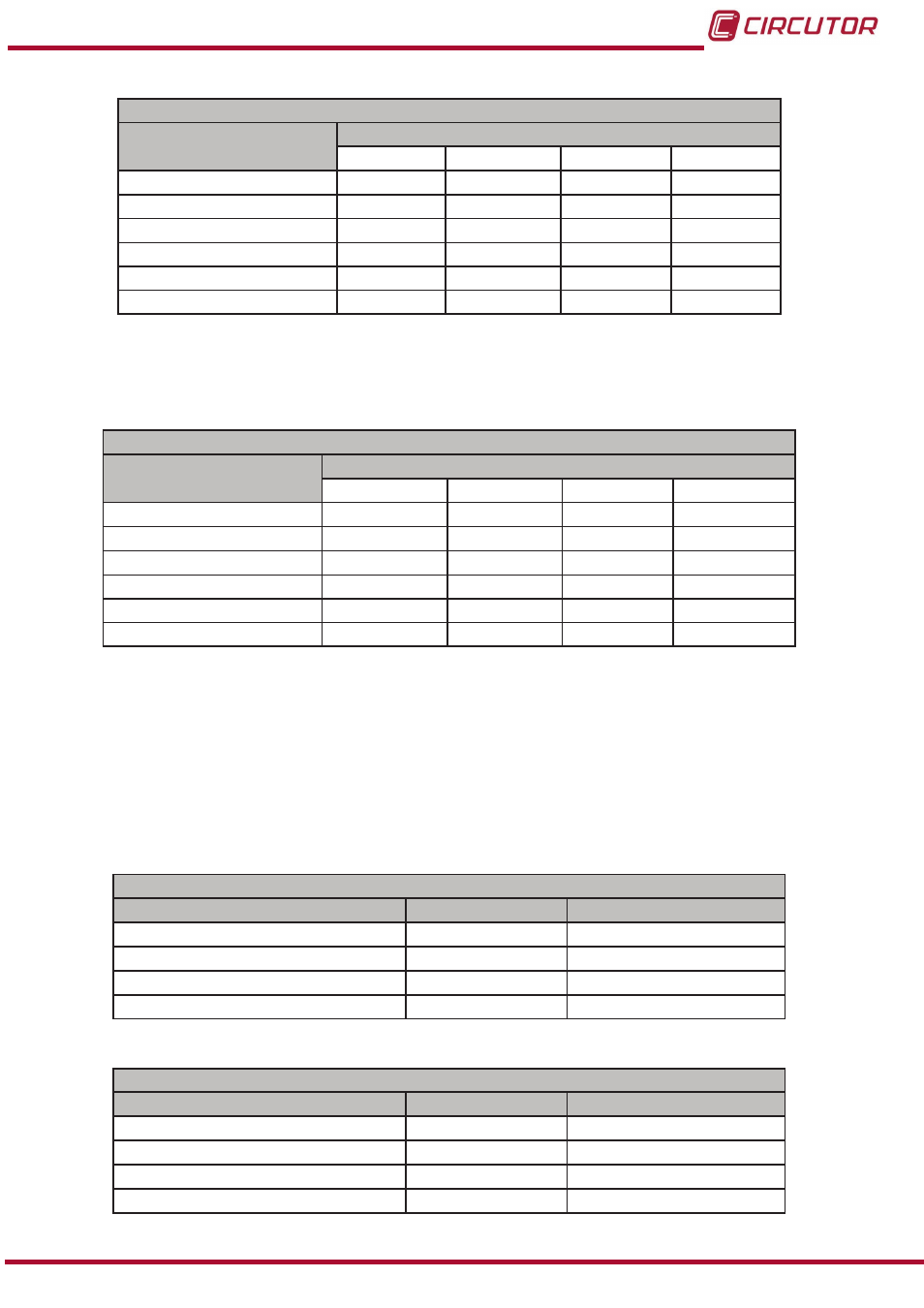
Table 119: Modbus memory map: Analogue inputs, expansion modules (Table 4)�
Configuration of analogue inputs: Slot 3
Configuration variable
Address
Input 1
Input 2
Input 3
Input 4
Zero
DAC0
DAD4
DAE8
DAFC
Full-scale
DAC1
DAD5
DAE9
DAFD
Scale
DAC2
DAD6
DAEA
DAFE
No. of decimals
DAC3
DAD7
DAEB
DAFF
Input name
DAC4 - DAC7 DAD8 - DADB DAEC - DAEF DB00 - DB03
Units
DAC8 - DACA DADC - DADE DAF0 - DAF2 DB04 - DB06
Note: The 11 registers must be written and read at once (as a group), otherwise it will respond
with an error.
Table 120: Modbus memory map: Analogue inputs, expansion modules (Table 5)�
Configuration of analogue inputs: Slot 4
Configuration variable
Address
Input 1
Input 2
Input 3
Input 4
Zero
DEA8
DEBC
DED0
DEE4
Full-scale
DEA9
DEBD
DED1
DEE5
Scale
DEAA
DEBE
DED2
DEE6
No. of decimals
DEAB
DEBF
DED3
DEE7
Input name
DEAC - DEAF
DEC0 - DEC3 DED4 - DED7 DEE8 - DEEB
Units
DEB0 - DEB2
DEC4 - DEC6 DED8 - DEDA DEEC - DEEE
Note: The 11 registers must be written and read at once (as a group), otherwise it will respond
with an error.
7�4�4�3�- Status of the analogue inputs
The following functions are implemented for these variables:
function 0x04: reading registers.
Table 121: Modbus memory map: Analogue inputs, expansion modules (Table 6)�
Status of the analogue inputs: Slot 1
Configuration variable
Address
Valid data margin
Status Input 1
D390 – D391
-
Status Input 2
D392 – D393
-
Status Input 3
D394 – D395
-
Status Input 4
D396 – D397
-
Table 122: Modbus memory map: Analogue inputs, expansion modules (Table 7)�
Status of the analogue inputs: Slot 2
Configuration variable
Address
Valid data margin
Status Input 1
D778 - D779
-
Status Input 2
D77A - D77B
-
Status Input 3
D77C - D77D
-
Status Input 4
D77E - D77F
-
257
Instruction Manual
CVM-B100 - CVM-B150