CIRCUTOR CVM-B Series User Manual
Page 256
7�4�4�2�- Programming analogue inputs
The following functions are implemented for these variables:
function 0x04: reading registers.
function 0x10:Writing multiple registers.
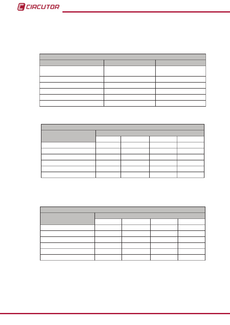
Table 116:Modbus memory map: Analogue inputs, expansion modules (Table 1)�
Configuration of analogue inputs
Configuration variable
Valid data window
Default value
Scale
0: 0 to 20 mA
1: 4 to 20 mA
0
Zero
-32000 to 32000
0
Full-scale
-32000 to 32000
20000
No. of decimals
0 to 5
0
Input name
(1)
8 characters
“--”
Units
(1)
5 characters
“--”
(1)
the characters must be sent in hexadecimal.
Table 117: Modbus memory map: Analogue inputs, expansion modules (Table 2)�
Configuration of analogue inputs: Slot 1
Configuration variable
Address
Input 1
Input 2
Input 3
Input 4
Zero
D2F0
D304
D318
D32C
Full-scale
D2F1
D305
D319
D32D
Scale
D2F2
D306
D31A
D32E
No. of decimals
D2F3
D307
D31B
D32F
Input name
D2F4 - D2F7 D308 - D30B
D31C - D31F D330 - D333
Units
D2F8 - D2FA D30C - D30E
D320 - D322
D334 - D336
Note: The 11 registers must be written and read at once (as a group), otherwise it will respond
with an error.
Table 118: Modbus memory map: Analogue inputs, expansion modules (Table 3)�
Configuration of analogue inputs: Slot 2
Configuration variable
Address
Input 1
Input 2
Input 3
Input 4
Zero
D6D8
D6EC
D700
D714
Full-scale
D6D9
D6ED
D701
D715
Scale
D6DA
D6EE
D702
D716
No. of decimals
D6DB
D6EF
D703
D717
Input name
D6DC - D6DF D6F0 - D6F3
D704 - D707
D718 - D71B
Units
D6E0 - D6E2
D6F4 - D6F6
D708 - D70A D71C - D71E
Note: The 11 registers must be written and read at once (as a group), otherwise it will respond
with an error.
256
CVM-B100 - CVM-B150
Instruction Manual