CIRCUTOR CVM-B Series User Manual
Page 46
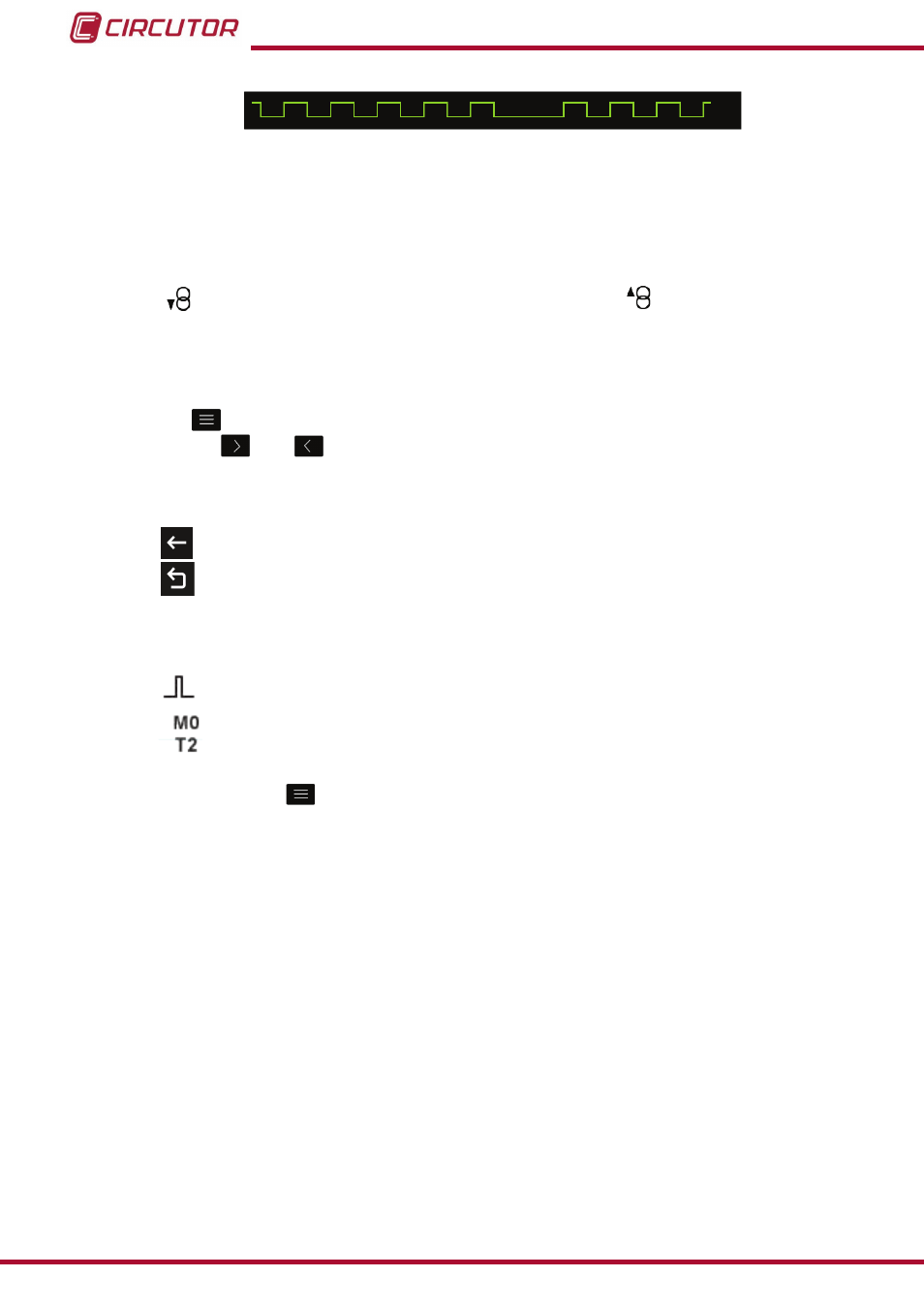
figure 35: graphical representation of the energy increase�
NB: This representation is not real, it is only significant to give the user an idea of the energy
increase.
(2)
The following icons appear for all these parameters on the screen:
Indicating that the parameter refers to consumed or
generated energy.
If the 2 icons light up at the same time, it means the installation is not properly connected.
(3)
The value of the energy parameters is saved in the non-volatile memory every minute.
Press the
key to display the lower area.
Use the keys
and
to browse the various parameters.
The menu in the lower area disappears after a few seconds.
The following icons also appear in the lower area:
Back, returns to the default parameters display screen,
figure 28�
Main Menu, back to the main menu,
figure 25
.
If there is a transistor digital output or input, programmed in impulse mode, associated with the
variable being displayed, the following will appear:
The icon that indicates that an impulse input or output has been programmed
The module with which the alarm is associated.
The associated output in the module.
If you press the key
while selecting a display parameter, you will enter the parameter
display menu.
46
CVM-B100 - CVM-B150
Instruction Manual