3 connecting output devices – AGI Security GV-CONCT User Manual
Page 37
GV-AS110 Controller
27
2
2.2.3 Connecting Output Devices
GV-AS110 supports 2 types of outputs:
1. Alarm outputs, e.g. siren or bell
2. Door outputs, e.g. electronic lock
The table below shows the wire assignments of output connectors on GV-AS110.
Wire color
Definition
Purple Alarm
COM
Gray Alarm
NO
Brown & White
Door COM
Black & White
Door NC
Light green
Door NO
Check if your output device meets the following absolute maximum ratings before
connecting it to the Door outputs.
Breakdown Voltage
250V AC, 220V DC
Continuous Load Current
1A (30V DC), 0.3A (125V AC)
Note: Absolute Maximum Ratings are those values beyond which damage to GV-
AS110 circuit board may occur. Continuous operation of GV-AS110 at the absolute
rating level may affect GV-AS110’s reliability.
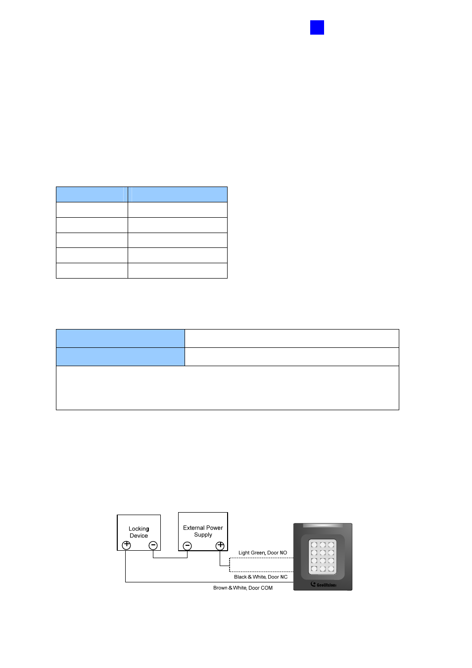
To connect an output device:
The example below illustrates the connection of a locking device to GV-AS110. Connect the
(+) point on the locking device to the Door COM wire on GV-AS110, connect the two (-)
points of the locking device and the external power supply together, and connect the (+)
point on the external power supply to the Door NO or Door NC wire on GV-AS110 based on
the state of the locking device.
1
2
3
4
5
6
7
8
9
*
0
#
Figure 2-4