4 installation, A connecting gv-as100/gv-as110 – AGI Security GV-CONCT User Manual
Page 95
Advertising
Optional Devices
85
4
4.1.4 Installation
This section describes how to connect other devices to GV-ASBox.
4.1.4.A Connecting GV-AS100/GV-AS110
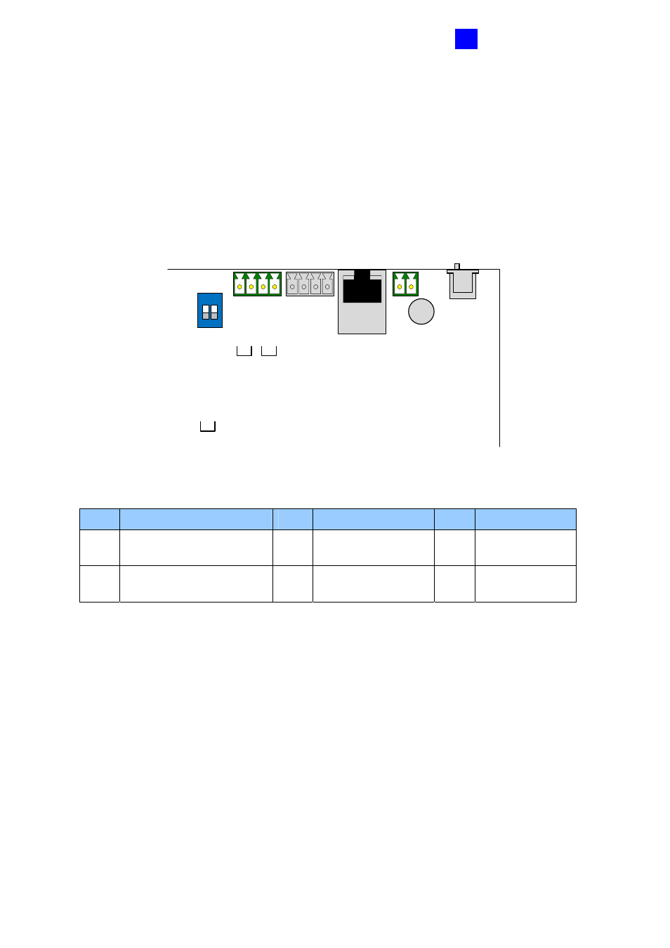
The table and figure below show the pin assignments of related connectors on GV-ASBox
for connection to GV-AS100 and GV-AS110
.
1 2
ON
GN
D
12
V
A+
A-
B+
B-
GV-AS100/110
GV-Rea
ders
RS-48
5_
A
TERM
RS-48
5_
B
TERM
Figure 4-2
Pin Function
Pin
Function
Pin
Function
12V
12V Power Supply to
GV-AS100/GV-AS110
A+
GV-AS100/GV-
AS110 Connection
B+
GV-Readers
Connection
GND
GND for Power Supply to
GV-AS100/GV-AS110
A-
GV-AS100/GV-
AS110 Connection
B-
GV-Readers
Connection
For connection to GV-AS100/GV-AS110, two switches (RS-485_A Term and RS-485_B
Term) must be turned ON.
Advertising
This manual is related to the following products: