D connecting input devices – AGI Security GV-CONCT User Manual
Page 97
Optional Devices
87
4
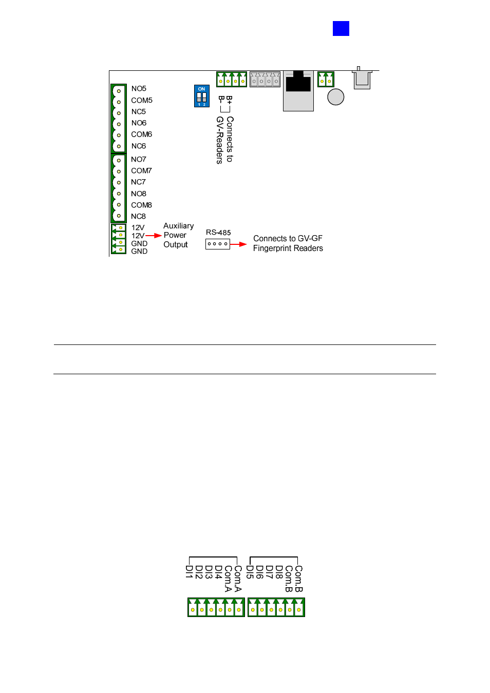
Figure 4-3
To define each GV-Reader and GV-GF Fingerprint Reader, you need to use the GV-
AS100/GV-AS110 Web interface. See 4.1.5.E.g Extended Reader Setting.
Note: The RS-485 connector on GV-ASBox is only designed for the connection of GV-
Readers and GV-GF Fingerprint Readers.
4.1.4.D Connecting Input Devices
GV-ASBox provides 8 inputs (DI1 to DI8).
All inputs are dry contact and can be configured
as normally open (NO) or normally closed (NC)
through the Web interface. The default value
is NO.
The figure below shows the pin assignments of input connectors on GV-ASBox. The 8 inputs
are divided into two terminals. Terminal A consists of DI1 to DI4, and terminal B includes DI5
to DI8. Every terminal has two COM (Common) points; connect the Common wire to any of
the two COM points on the related terminal.
Figure 4-4