AGI Security GV-CONCT User Manual
Page 58
Advertising
48
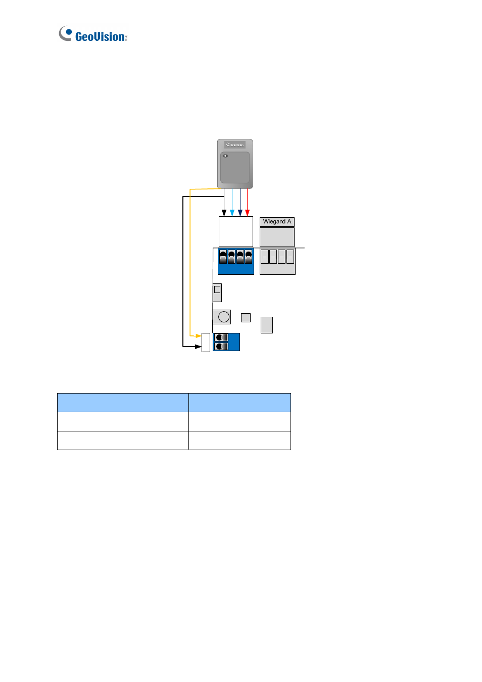
If your card readers are equipped with LED or beeper that can be controlled externally,
connect the control wires to outputs 9 ~ 16. The following figure and table shows how to
connect the beeper wire of GV-Reader to GV-AS400.
GN
D
RS485
-
RS485
+
12V
GN
D
D0
D1
12V
+O
UT
09-
Figure 3-7
Electric Wires on GV-Reader Output on GV-AS400
Yellow (Beeper)
Output +
Black (GND)
Output -
The SW1 on GV-Reader must be turned OFF so that the beeper can be controlled by GV-
AS400.
Advertising
This manual is related to the following products: