Introduction, Modular service tool and system manager, Vcm-x / rne operator interfaces technical guide 3 – Orion System VCM-X/RNE Operator Interfaces User Manual
Page 3: Modular system manager, Modular service tool, Figure 2: modular system manager dimensions, Figure 1: modular service tool dimensions
VCM-X / RNE Operator Interfaces Technical Guide
3
INTRODUCTION
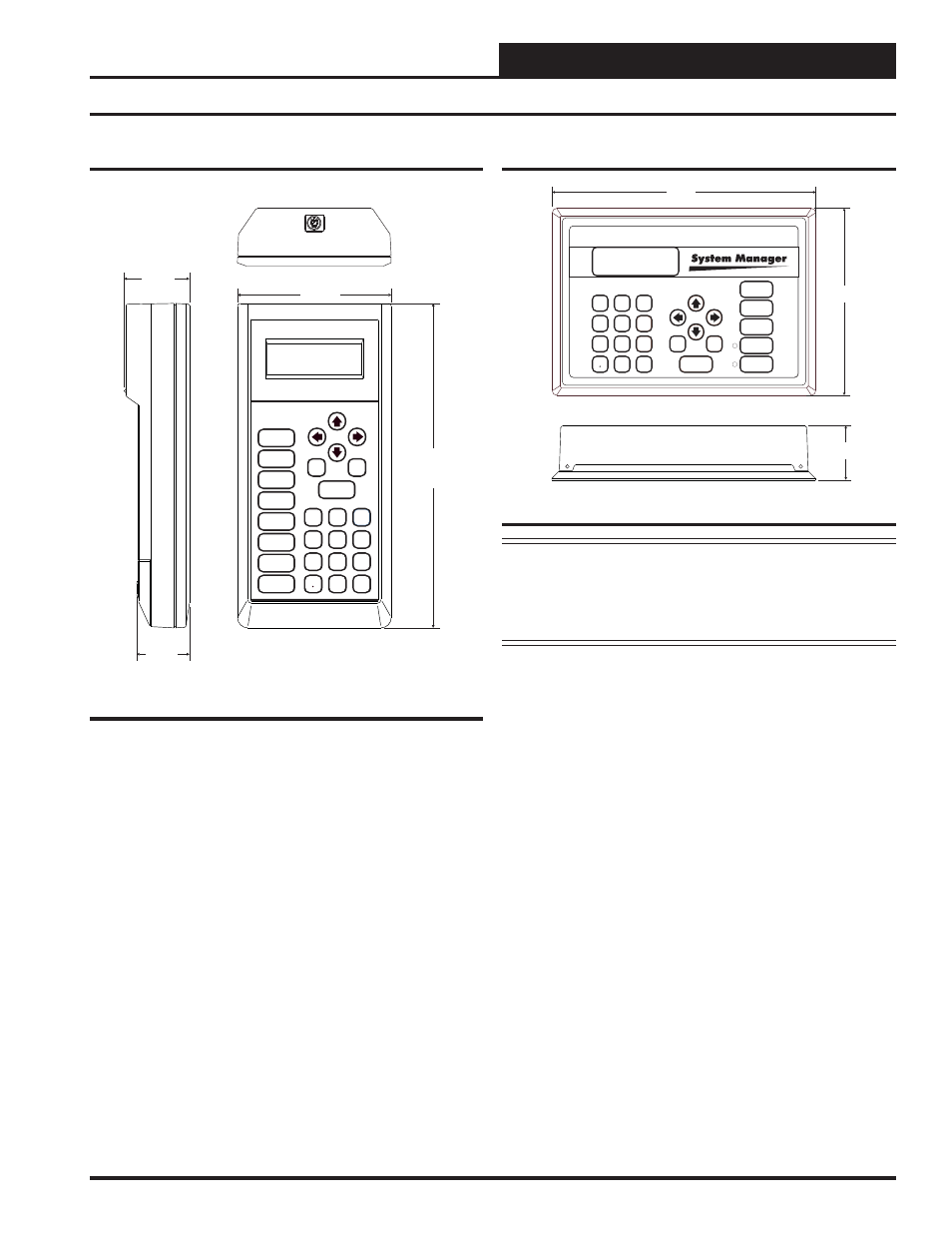
Modular System Manager
ENTER
CLEAR
ESC
PREV
NEXT
DOWN
UP
6
5
4
DEC
7
0
8
1
3
2
9
MINUS
-
STATUS
SETPOINTS
SCHEDULES
ALARMS
OVERRIDES
9.00"
6.25"
1.81"
Figure 2: Modular System Manager Dimensions
NOTE:
The Modular System Manager can be used with the
VCM-X Controller, but not with the RNE Controller. The
interface options for the RNE Controller are the Modular
Service Tool, the System Manager Touch Screen II, or
Prism II Software.
The OE392-07 Modular System Manager provides a direct link to en-
able you to view the status and adjust the setpoints of the VCM-X and
VAV/Zone controllers on the control system communications loop. The
System Manager is housed in an attractive, off-white colored plastic en-
closure. The System Manager is equipped with a 4-line-by-20-character
backlighted display panel and a 24-key membrane keypad for data selec-
tion and entry. All keypad operations are simple and straight forward,
utilizing non-cryptic plain English language messages. Menu-driven
programming allows for easy setup and operation without the need for
specialized training. The System Manager also has 2 integral LEDs for
user notifi cation of system alarm conditions and override initiations.
Protection from unauthorized users is provided by the System Manager’s
integral multi-level passcode authorization programming.
On a Networked System, the Modular System Manager is connected to
the communications and power loop of the system via modular cables
that simply plug into the System Manager board and the Power/Comm
Distribution Board. This virtually eliminates wiring errors and makes
installation fast and easy. When it is to be connected to a Stand-Alone
system, a cable with modular connectors on one end and stripped wire
ends on the other end is provided to facilitate connecting communications
and power to the Modular System Manager from the 24 VAC power
source and the HVAC unit controller communication wiring terminals.
The Modular System Manager is designed for wall mounting. Mounting
holes are provided to attach the Modular System Manager to a standard
handy box. It is recommended that the System Manager be mounted at
approximately eye level to allow for ease of programming and reading
of the display. The System Manager is typically mounted in the build-
ing manager’s or superintendent’s offi ce or in an equipment room. The
attractive enclosure is quite suitable for mounting in any location.
Modular Service Tool and System Manager
Modular Service Tool
Mode
Selection
ENTER
CLEAR
ESC
PREV
NEXT
DOWN
UP
6
5
4
DEC
7
0
8
1
3
2
9
MINUS
-
STATUS
SETPOINTS
SCHEDULES
CONFIGURATION
ALARMS
ON
OVERRIDES
BALANCE - TEST
10.00”
4.75”
2.02"
1.63"
Figure 1: Modular Service Tool Dimensions
The OE391-11 Modular Service Tool is a system operator interface that
provides a direct link to enable the system operator to view the status,
confi gure, and adjust the setpoints of the VCM-X, RNE, or VAV/Zone
Controller on the control system communications loop. The Modular
Service Tool is housed in an attractive beige-colored plastic enclosure.
The display area is covered with a clear plastic bezel for protection of the
display screen. The Modular Service Tool has a 4-line-by-20-character
display panel with adjustable contrast control and a 27-key membrane
keypad for data selection and entry. All keypad operations are simple and
straight forward, utilizing non-cryptic plain English language messages.
Menu-driven programming allows for easy setup and operation without
the need for specialized training. The Modular Service Tool is supplied
with (4) AA 1.5 V Volt alkaline batteries, a wall mount DC power sup-
ply and a communication cable terminated with an 8-pin DIN connector
for connection to the Service Tool. The cable allows you to setup and
program any Orion controller with an 8-pin DIN connector socket by
simply plugging the service tool into the socket on the controller.
The Modular Service Tool is designed to be hand-carried. Its rugged
plastic housing provides superior protection for the electronic compo-
nents housed inside. The Modular Service Tool is a top-quality service
tool that will stand up to the demands of the typical job site environment
for many years.