Vav/zone controller programming, Vav/zone confi guration screens, Vcm-x / rne operator interfaces technical guide 58 – Orion System VCM-X/RNE Operator Interfaces User Manual
Page 58: Vav zone confi guration
VAV/ZONE CONTROLLER PROGRAMMING
VCM-X / RNE Operator Interfaces Technical Guide
58
VAV/Zone Confi guration Screens
VAV Zone Confi guration
In order to correctly set up the VAV/Zone Controller, you must fi rst
confi gure several parameters in regard to the type of system and operat-
ing parameters for the VAV/Zone Controller you have installed. Most
of these values and operating parameters are only set once at the initial
system setup and are never changed.
System Manager Instructions
From any Menu Screen, press the
<SETPOINTS>
button. The Unit
Selection Screen will appear requesting that you enter the unit ID number.
Enter the correct unit ID number of the VAV/Zone Controller you want
to confi gure and press
<ENTER>
. You will see the screen shown below.
1) Change Setpoint
2) Configure Unit
3) Damper Force
ESC) Exit Menu
Press
<2>
on the keypad to enter the fi rst Unit Confi guration Screen.
Modular Service Tool Instructions
From any Menu Screen, press the
<CONFIGURATION>
button. The
Unit Selection Screen will appear requesting that you enter the unit ID
number. Enter the correct unit ID number of the VAV/Zone controller
you want to confi gure, and press
<ENTER>
. You will then see Unit
Confi guration Screen #1.
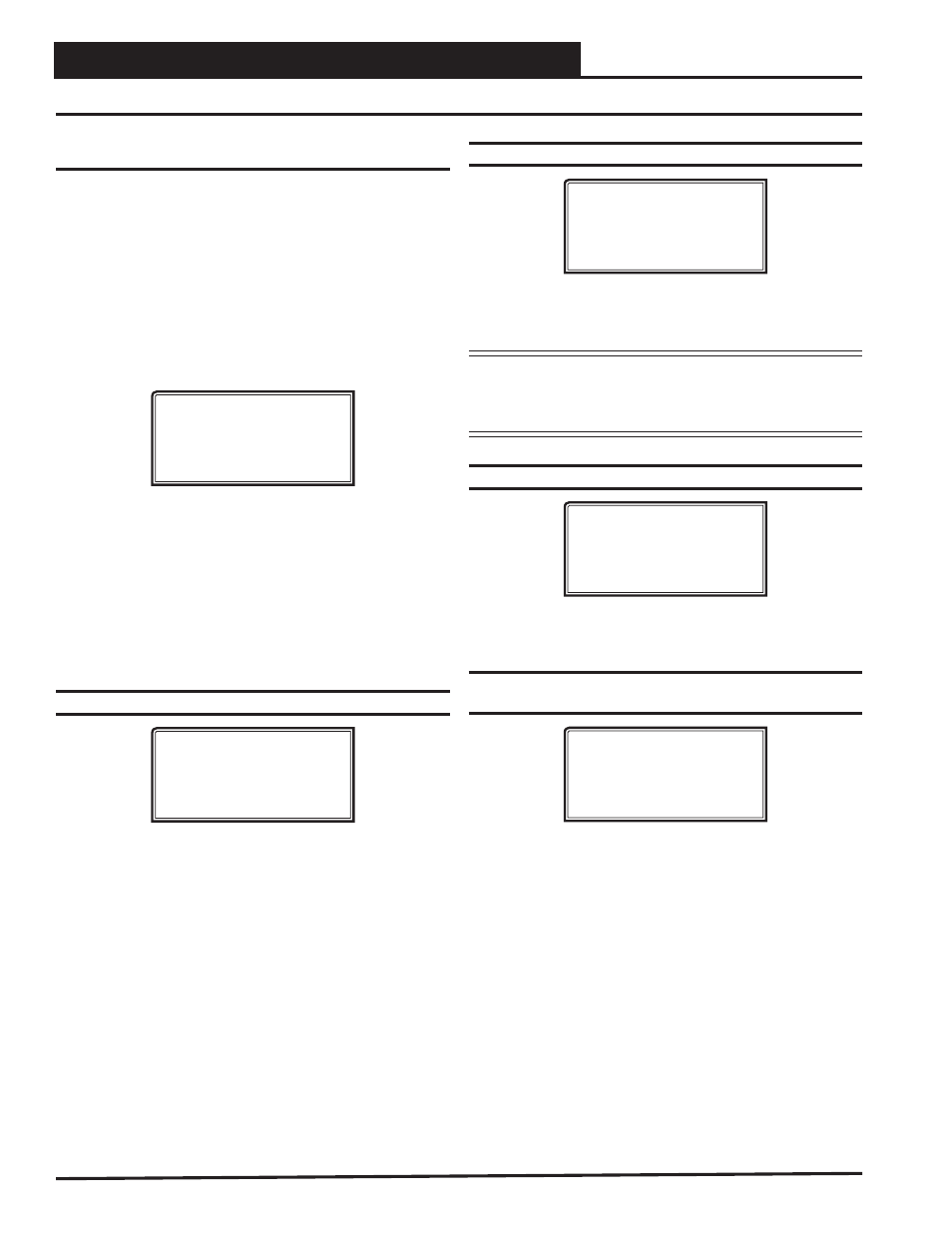
Confi guration Screen #1 - Box Confi guration
XX Box Cnfg IDXXXX
Box Configuration
COOLING ONLY BOX
[Enter Type 0 - 3]
This Box Control Code will operate in one of four possible modes. The
box designation will display on the top line of all screens.
0 = COOLING ONLY BOX (will display as CO Box)
1 = H/C CHANGEOVER BOX (will display as HC Box)
2 = SERIES FAN BOX (will display as SF Box)
3 = PARALLEL FAN BOX (will display as PF Box)
Confi guration Screen #2 - Damper Operation
XX Box Cnfg IDXXXX
Damper Operating
Mode: DIRECT ACTING
[0=Direct 1=Reverse]
Enter
<0>
for Direct Acting or
<1>
for Reverse Acting. If the damper
opens in a clockwise direction, it is DIRECT ACTING. If the damper
opens in a counter-clockwise direction, it is REVERSE ACTING.
CAUTION: If you change this setting, you MUST cycle
power to the controller to allow it to re-calibrate
the damper feedback positions for its new
direction of control!
Confi guration Screen #3 - Voting Zone
XX Box Cnfg IDXXXX
Is This Box a
Voting Zone..: YES
[0=NO 1=YES]
If this is a Zoned System, select this option so that the box can be in-
cluded as a voting zone.
Confi guration Screen #4 - Pressure
Independent Airfl ow Constant
XX Box Cnfg IDXXXX
Pr Independent Boxes
Airflow @ 1” WG
Constant..: 1200 CFM
If this is a Pressure Independent Box, you must enter this airfl ow
constant so that the CFM readings can be correctly calculated. This
airfl ow constant is provided by the box manufacturer and depends on
the diameter of the duct.