Communications -2 – Basler Electric DGC-2020 User Manual
Page 290
Communications
If the engine has an ECU (electronic control unit) and the DGC-2020 is to communicate with it, the
communications must be set up.
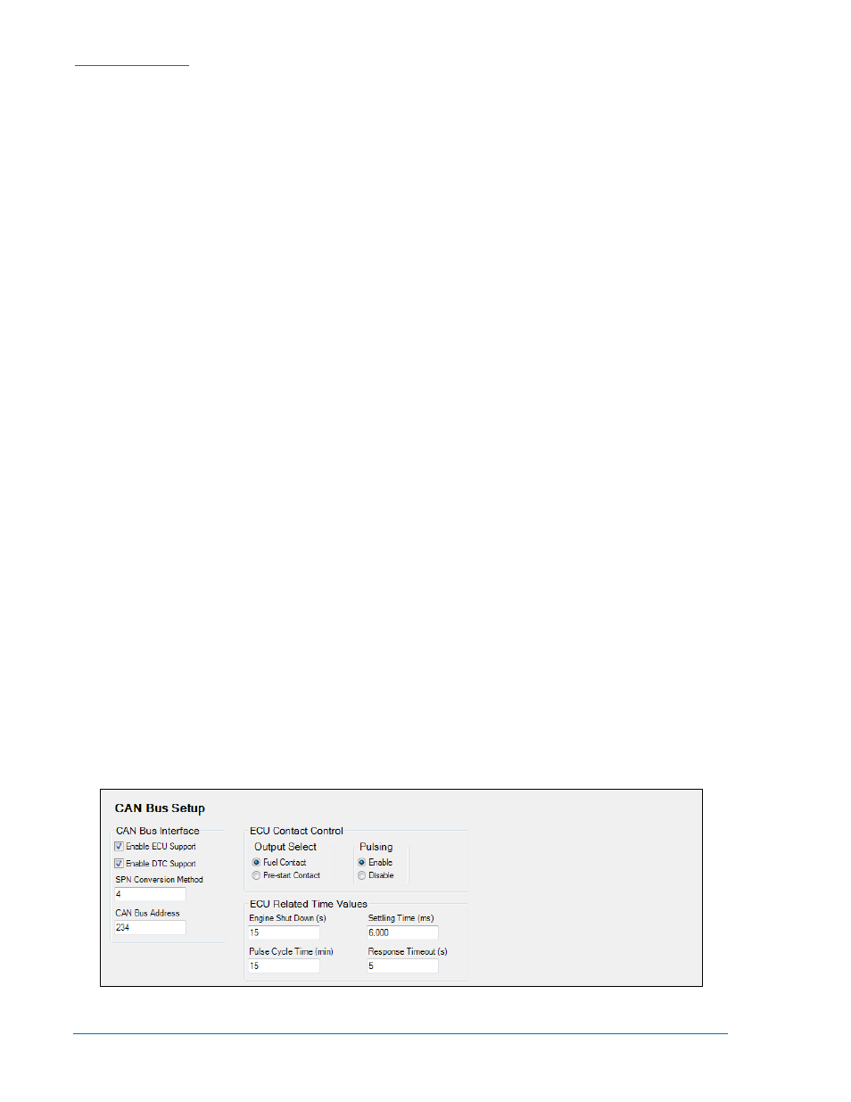
CAN Bus Setup (Figure 7-2)
Front Panel Navigation Path: SETTINGS > COMMUNICATIONS > CAN Bus SETUP
1. Enable ECU Support - Set to Enabled for the DGC-2020 to communicate with the ECU.
2. Enable DTC (Diagnostic Trouble Code) Support - If the ECU is a J1939 ECU, enable DTC support. If
the engine ECU does not support it, no diagnostic trouble codes will be logged by the DGC-2020.
3. SPN Conversion Method - When this bit is a zero, the conversion method is indicated as version 4.
The DGC-2020 will automatically set the conversion method to 4 when the CM bit is zero; this occurs
for most engine types. However, if the CM bit is 1, indicating the SPN conversion method is NOT 4,
the user will have to consult the engine manufacturer to learn the correct method of SPN conversion,
and set the SPN Conversion Method setting in the DGC-2020 accordingly.
4. CAN Bus Address - This parameter sets a unique address number for the DGC-2020 operating on a
CAN bus network. The CAN bus Address is set internally by the DGC-2020 when certain types of
ECUs are selected on the ECU Setup screen, and in this case, the user-entered value does not
apply.
5. ECU Contact Control - Output Select - Select whether the RUN output relay or the PRE (Prestart)
output relay will close to give the ECU its “energize to run” signal. In some implementations, this relay
may actually be providing ECU power.
6. ECU Contact Control - Pulsing Enable - Select if the ECU is not to be on line at all times. Often ECUs
are allowed to go “off line” to conserve battery drain when the engine is not running. The DGC-2020
will “pulse” it periodically to force it to be active to allow the DGC-2020 to read data such as coolant
temperature and coolant level. This is required if the DGC-2020 is to report low coolant temperature
conditions (which may indicate a failure of a block heater), or low coolant level conditions (if a leak
occurs while the machine is not running). Pulsing is also used to check the integrity of CAN bus
communications when the machine is not running.
7. ECU Related Time Values - Engine Shut Down - Set this parameter for a value longer than the
duration required to stop the engine after being shut down. The ECU is pulsed after this time expires.
If the time is too short, the pulse may occur while the engine is still turning which could cause a brief
re-start and possibly damage the flywheel and starter system.
8. ECU Related Time Values - Pulse Cycle Time - Set this parameter for the desired time between ECU
pulse cycles.
9. ECU Related Time Values - Settling Time - This parameter is the duration of the “on line” time of the
pulse cycle during which the DGC-2020 reads data from the ECU. The settling time should be set
long enough so that any ECU parameters that require time to “settle down” after the ECU is on line
can do so. Since the DGC-2020 may use some of the ECU data for alarm or pre-alarm annunciation,
it is important that the data have time to settle.
10. ECU Related Time Values - Response Timeout - This setting defines the amount of time that the
DGC-2020 will wait to receive data from the ECU during a pulse cycle or start attempt. If no data is
received during this time in a pulse cycle, a LOSS OF ECU COMMS pre-alarm is annunciated. If no
data is received in this time during an engine starting attempt, a LOSS OF ECU COMMS alarm is
annunciated.
Figure 7-2. Settings Explorer, Communications, CAN Bus Setup Screen
7-2
DGC-2020 Setup
9400200990 Rev X